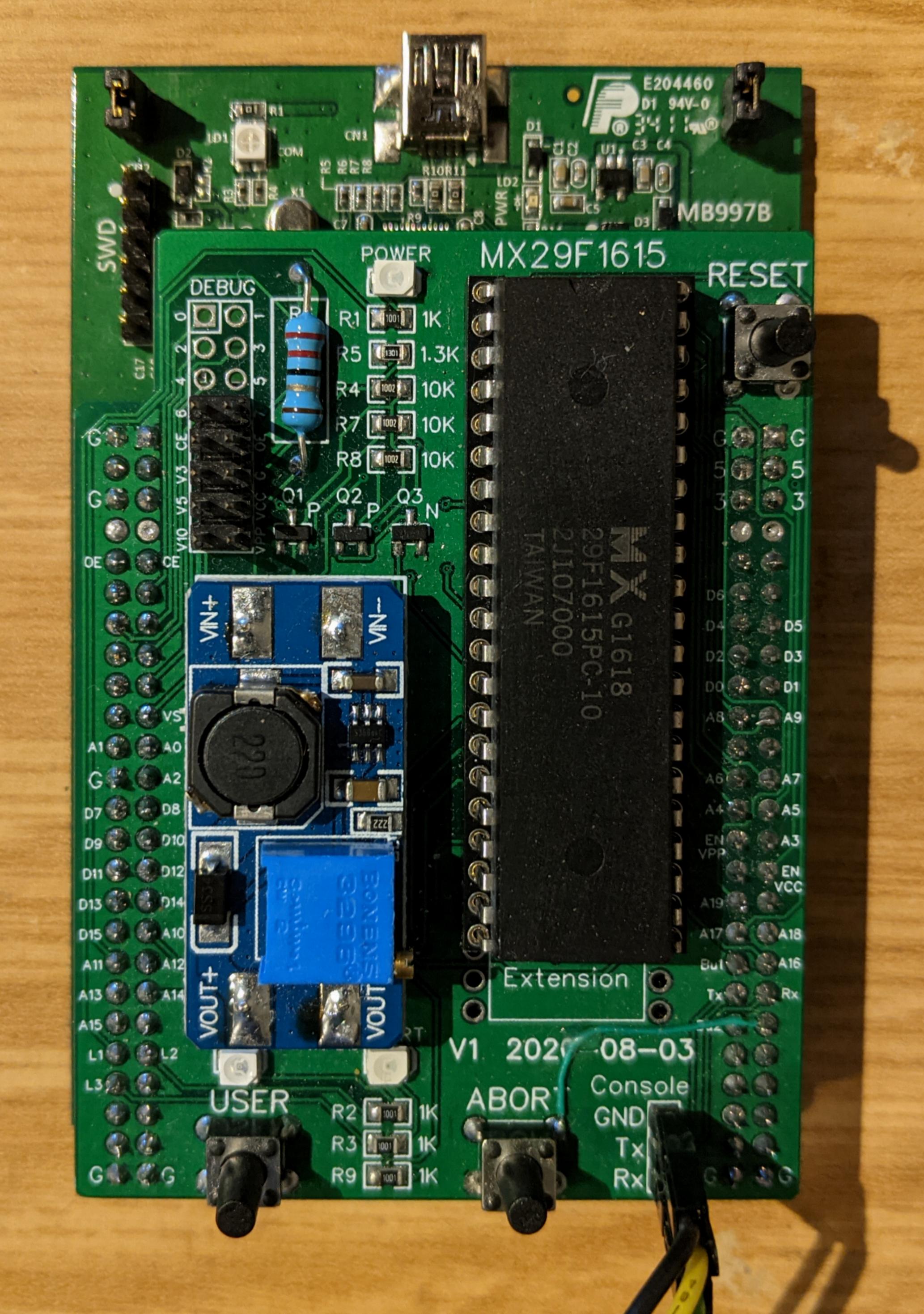
Rev 1
I wanted something simple to start developing firmware for the programmer, so Rev1 was implemented as a daughterboard which plugs into the pin headers of the STM32F4-Discovery board. The CPU on the ST-Micro STM32F4-Discovery is an STM32F407, which is a Cortex-M4 clocked up to 168 MHz. I already had several of these boards in my project bin from past projects.
The blue submodule you see on top of my board is an eBay MT3608 DC-DC Step-Up Converter module which has been tuned to boost the 5V from USB to the 10V required by the MX29F1615 for programming/erase cycles.
This revision of the board is not very complicated, with three LEDs, three buttons, three MOSFETs, a handful of resistors, and a few connectors. Most of the complexity in this 2-layer board was in routing Discovery board pins to the EEPROM socket.
You might notice one rework wire. I moved a button from PA14 to PA15 because PA14 is reserved for SWD by the ST-Link programmer. If firmware reconfigures PA14 as an input with pull-up (as was needed), it would disable the ability of the ST-Link to take over and reprogram the flash.
|

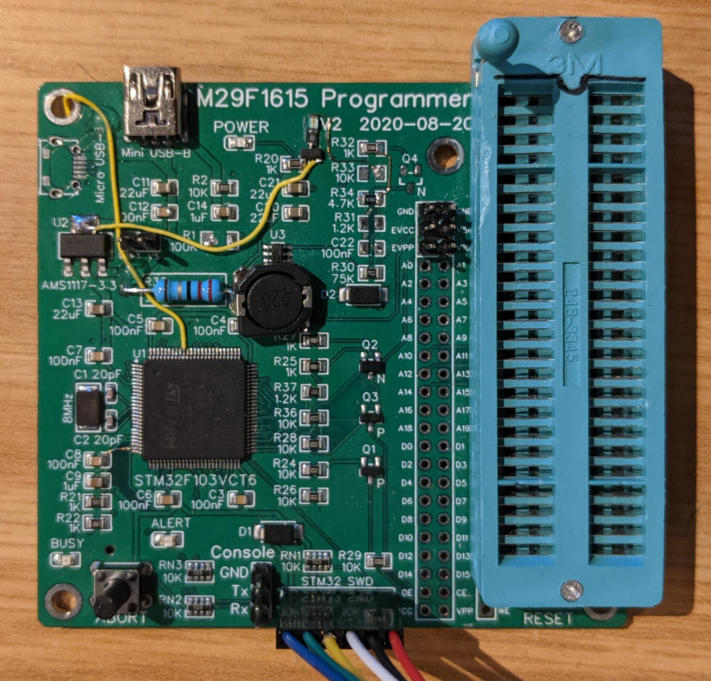
Rev 2
This revision of the board brings onboard an STM32F103 MCU, AMS1117-3.3 voltage regulator, and the MT3608 for 10V supply. The STM32F103 is a Cortex-M3 CPU with 256KB of flash and 48K of SRAM. Quite a bit less than the STM32F407, but still considerably more than I need to implement the programmer.
You may notice the ST-Link header and cable. I use this to program the board, using the ST-Link on the STM32F4-Discovery board as a programmer.
I began adding voltage monitors to this board, which is why you see one or two of the rework wires. Also, I failed to notice that I needed an external pull-up resistor for USB in the design. This caused the unmodified board to not be noticed by the USB host. The MT3608 section also required a lot of changes. I wanted the STM32 MCU to be able to sense and adjust the voltage being regulated by the MT3608 so that it didn't require manual tuning. It took several tries, but I finally figured out a circuit which does what I want. This circuit was implemented in Rev 3 of the board.
|
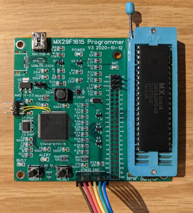
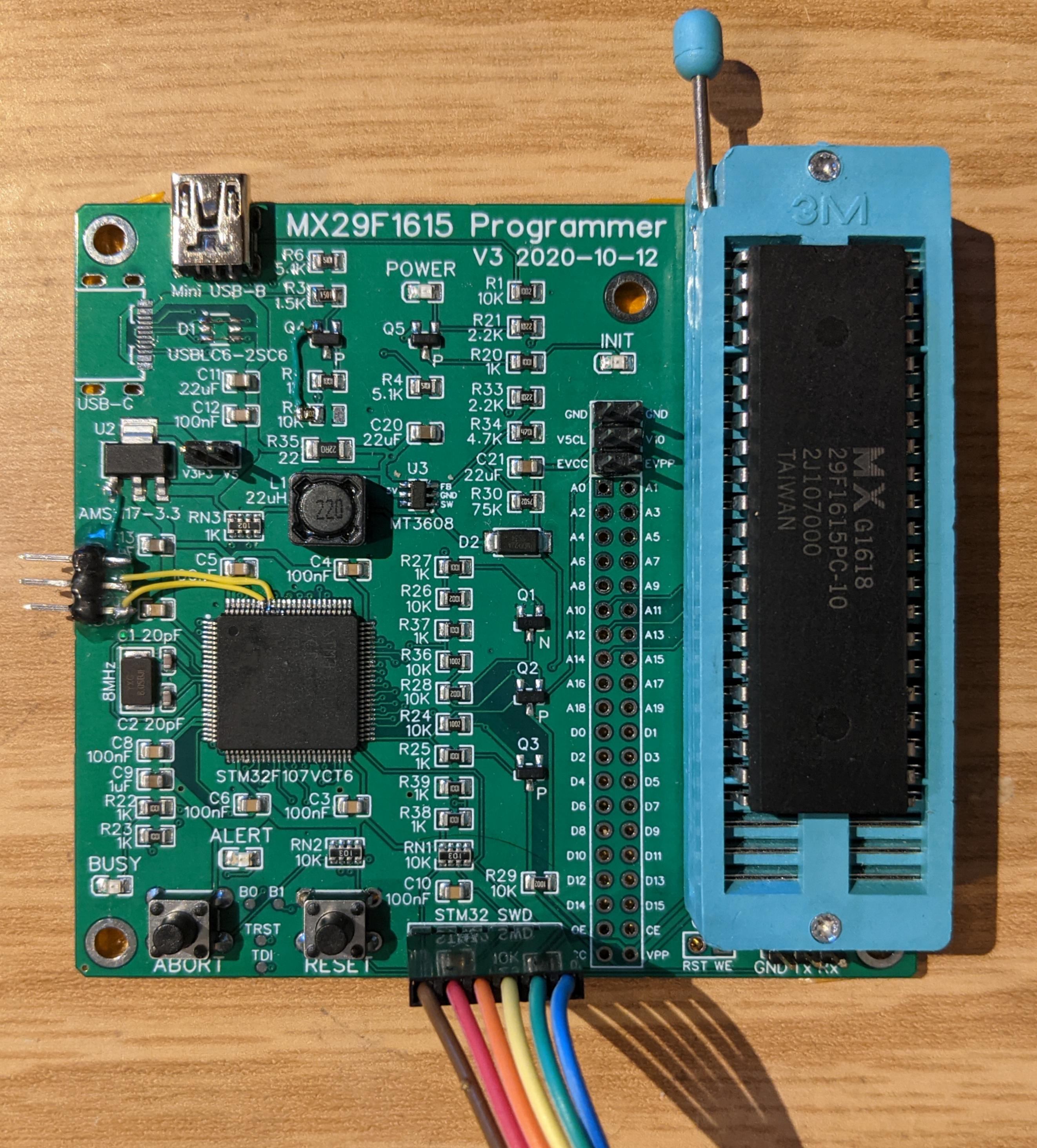
Rev 3
This revision of the board replaces the STM32F103 with an STM32F107. I changed the MCU because the STM32F103 ROM does not support USB DFU. I was hoping to be able to allow the use of USB DFU for others to program the board without requiring an ST-Link. Other nice features of the STM32F107 include an internal USB D+ pull-up and larger USB buffers.
This board has rework. The big issue I ran into was that the USB device in the STM32F107 USB core requires sensing the USB VBus signal. This particular pin is not remappable in the core and happens to overlap the serial console Tx pin that I had been using. So every time software would emit text on the serial console, the USB pull-up would get dropped by the core. So the new header you see implements the move of the console UART to the alternate GPIOs. This will be part of the Rev 4 board.
This version of the board also has a place for a USB EMI filter. I'm not certain if the filter adds anything, and on this particular board I've removed the part and replaced it with jumper wires.
Another change I made is to swap out the optional Micro USB connector for a Type C connector. When routing the PCB, I wasn't aware of the fact that the part I chose actually requires a board cut out under the part. I used a dremel and manually cut out the area to test the USB-C before spinning the Rev 4 board.
|
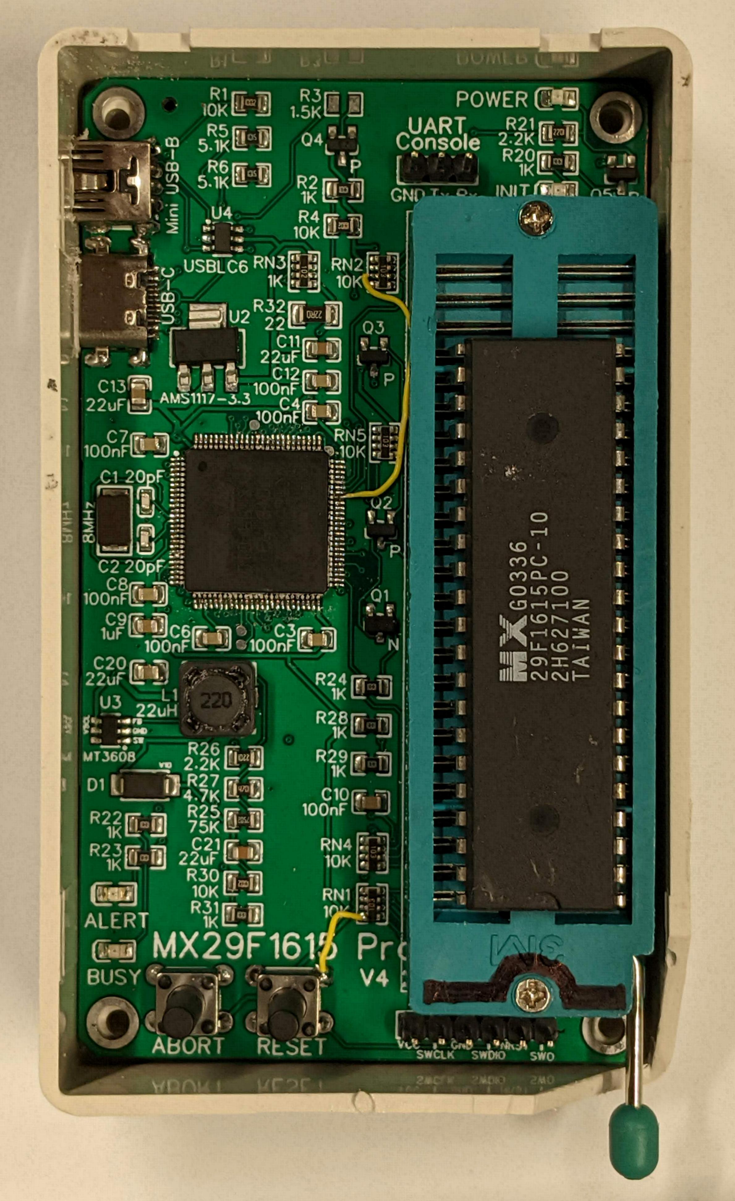
Rev 4
As you can see from the photo on the right, the layout for this design has been shrunk to fit in a readily available 100x60mm project box. The box needs minor modifications (dremel) for the USB ports and the ZIF socket handle, but these are relatively minor items.
This revision of the board continues to use either the STM32F107 or STM32F105. If you are building your own board, the STM32F103 may also be used, but in that case R2, R3, R4, and Q4 must be populated for this part to work. Also, the firmware must be compiled for STM32F103 (BOARD_REV=2) as the USB device hardware is different from the F105 and F107 parts. If you are instead using an F105 or F107, then make sure that at least R3 is removed.
Bugs
- PA10 has VBUS pull-up, but it should be on PA9. The easiest solution is to bridge PA9 and PA10 on the CPU. A more difficult solution (shown in the photo on the right) is to cut the pullup trace to PA10 and connect it to PA9. The complicated rework is then cut trace to second from bottom left of RN2 and run wire to PA10 on the STM32.
- BOOT1 is pulled high instead of being pulled low. This prevents DFU mode from working (to load firmware). Fix by cutting left trace to RN1 bottom left lead and instead run that lead to GND (top right of RESET button).
- PD6 should only be pulled low at startup. This is complicated to rework fix because it involves adding a MOSFET that is gated by the Init LED signal.
|
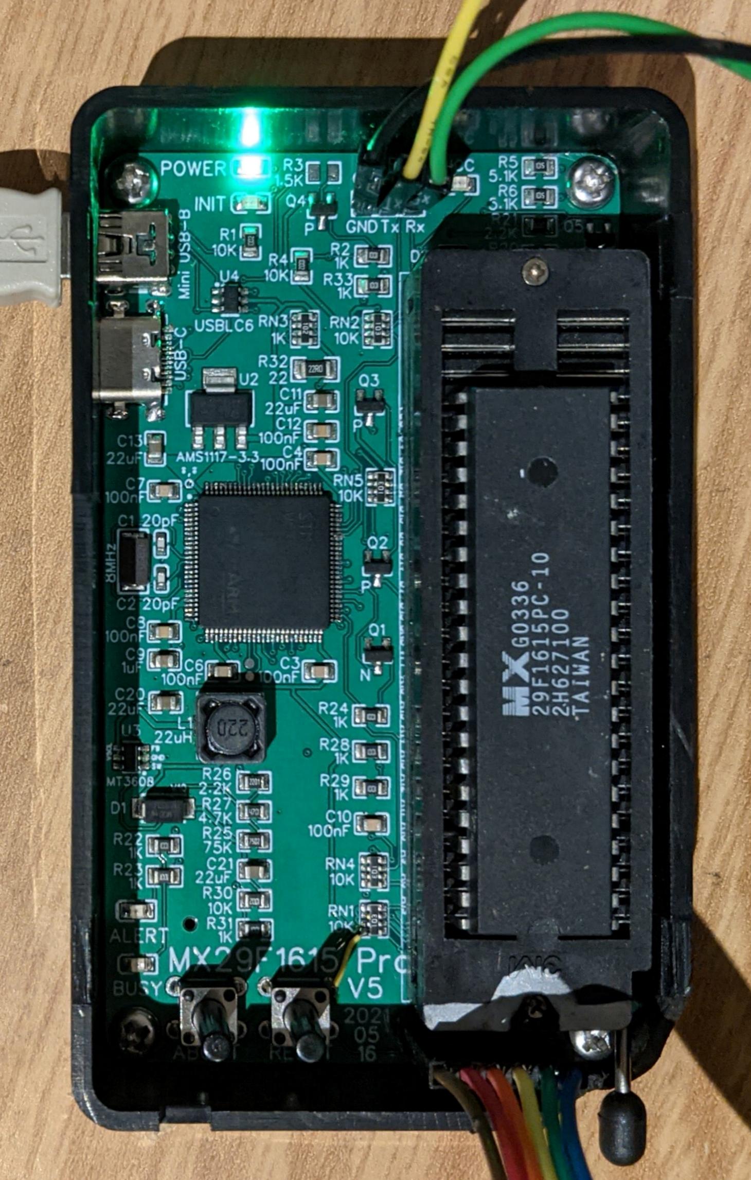
Rev 5
This version represents only minor modifications the Rev 4 design. The Power and Init LEDs have moved to the upper left for better visibility. A new "power is applied to the socket" LED is now in the upper right of the board. The "VCC Active" LED will turn off automatically after about 1 second (up to firmware) after last access.
This board fixes the PD6 pull-down to only occur at startup. The USB-C cutout area was adjusted to give more contact area for the pads. The board was narrowed slightly to fit the case better.
Bugs
- PA10 has VBUS pull-up, but it should be on PA9. The easiest solution is to bridge PA9 and PA10 on the CPU.
- BOOT1 is pulled high instead of being pulled low. This prevents DFU mode from working (to load firmware). Fix by cutting left trace to RN1 bottom left lead and instead run that lead to GND (top right of RESET button).
- Board corners need to be rounded more to fit the case easier.
|
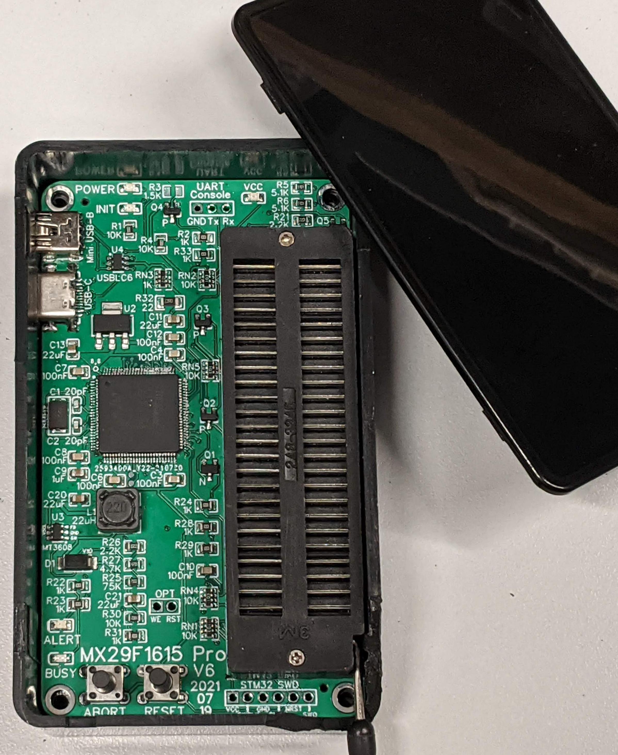
Rev 6
This is the final version of the MX29F1615 programmer. It has fixes for following flaws in the Rev 5 board:
- VBUS pull-up is now on PA9.
- Boot1 is now pulled low instead of being pulled high.
- Depth of USB-C cutout is reduced by 0.5mm.
And the following enhancements:
- Corners pulled in and board is slightly narrower for easier fit in case.
- Added GPIOs to the extension spares on the ZIF socket.
- Added OPT header with WE and RST pins.
|