WD33C93 and compatible SCSI controllers
Western Digital WD33C92
DIP-48 or QSM-44 (quad surface mount)
Western Digital WD33C93
DIP-40 or QSM-44 (quad surface mount)
Synchronous SCSI: Maximum 4 MB/sec
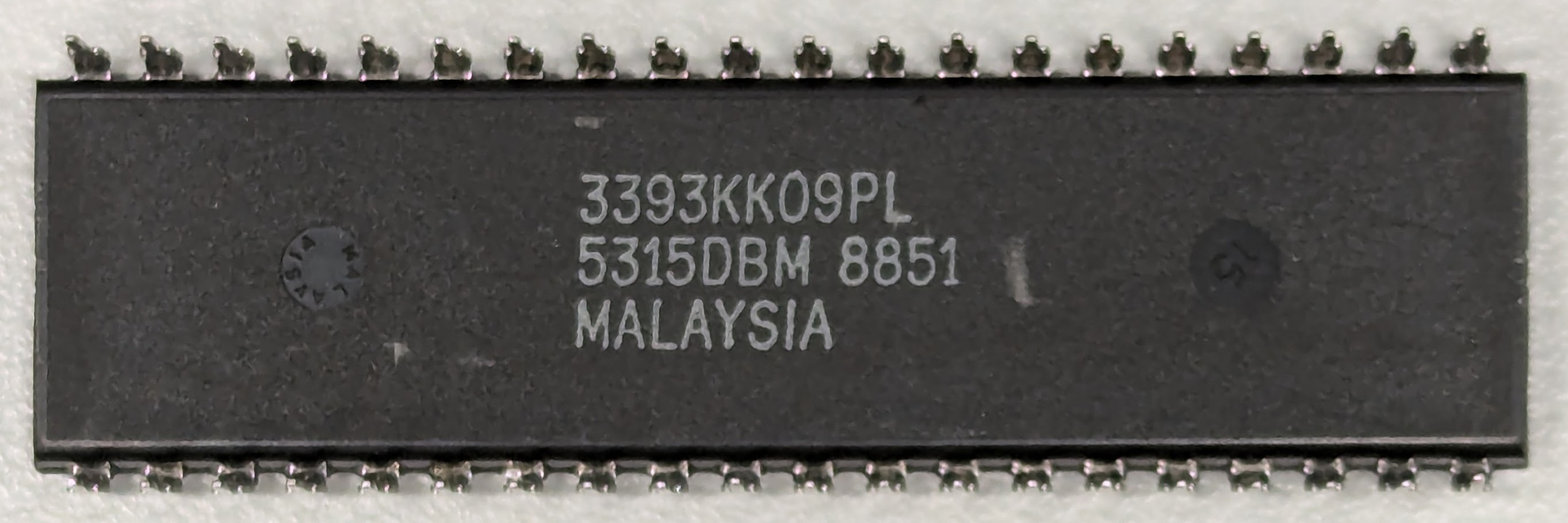
The 3393 code, as seen on the bottom of the ASIC, is the manufacturer code for the WD33C93 product.
Known versions:
WD33C93-PL 00-02 microcode ?09? not software-readable
Known production: 8849

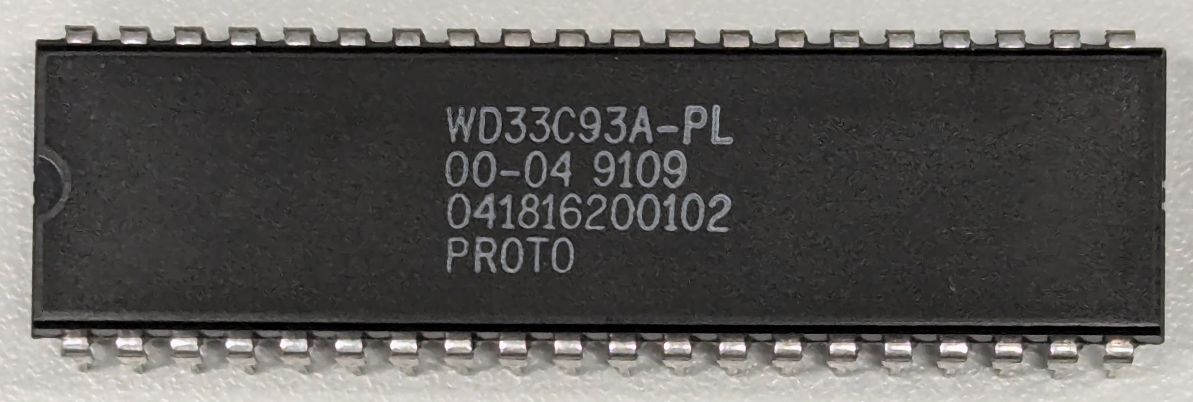
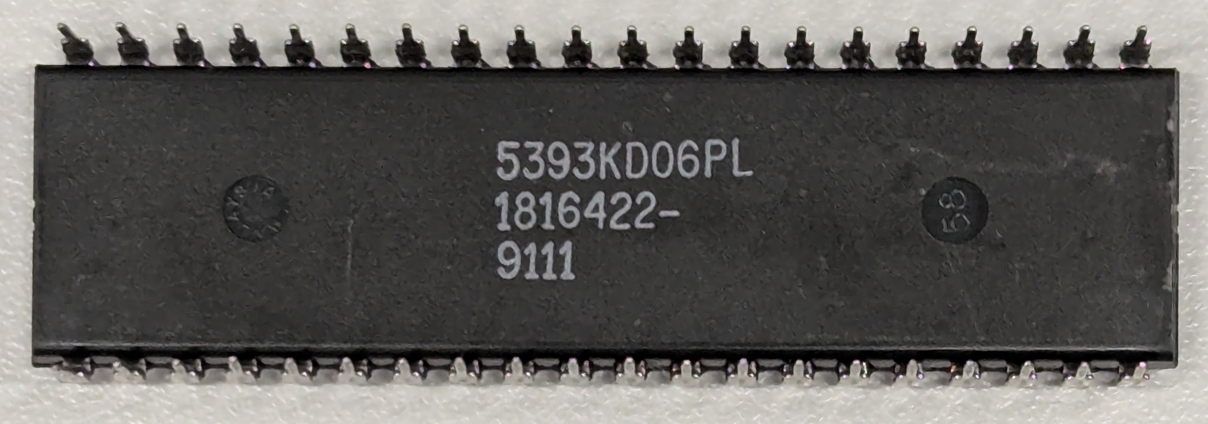
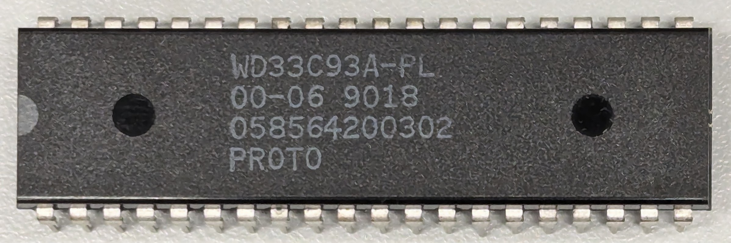
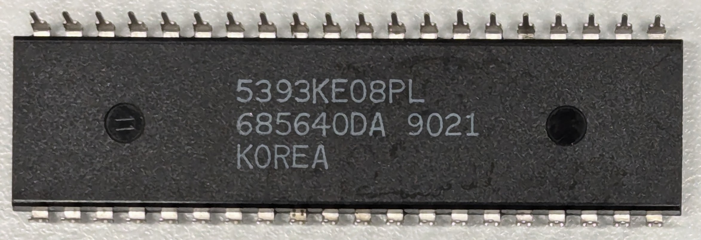
Western Digital WD33C93A
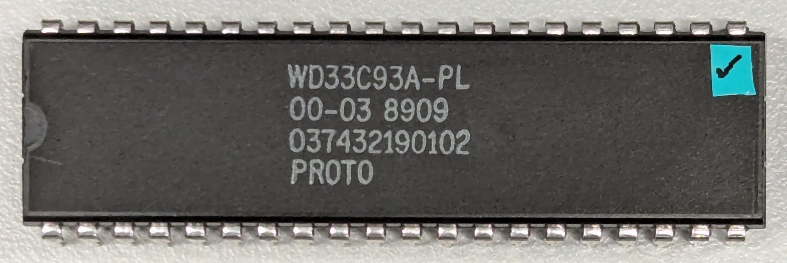
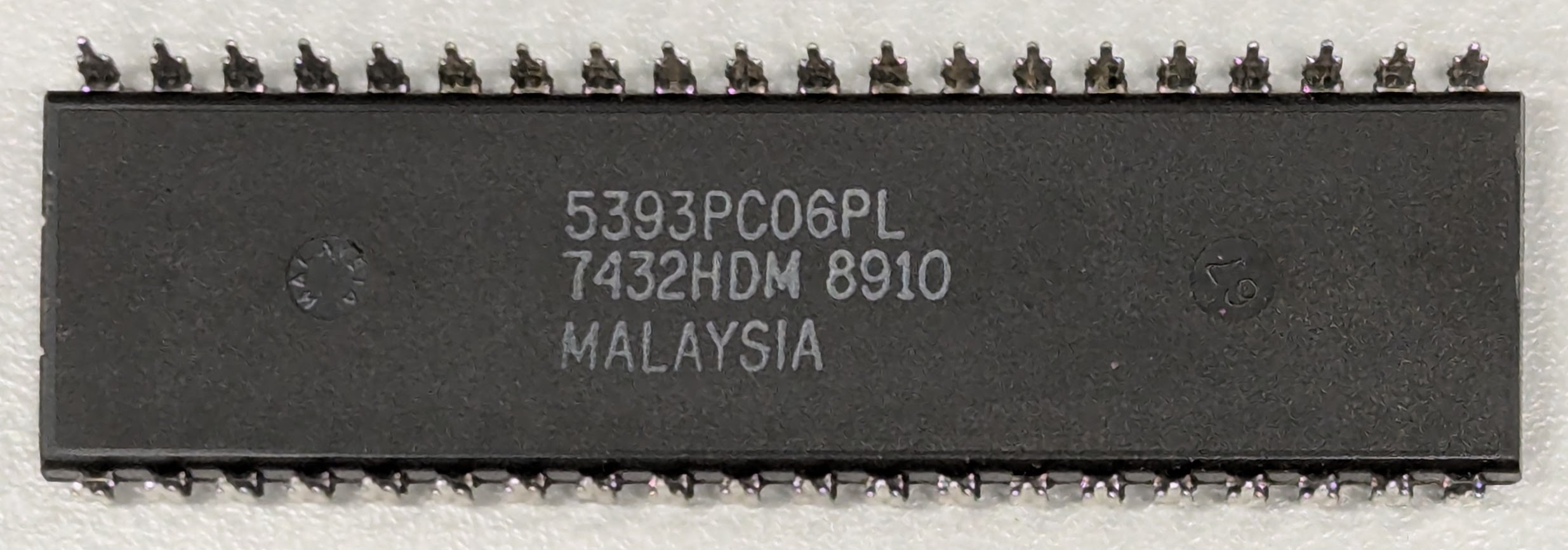
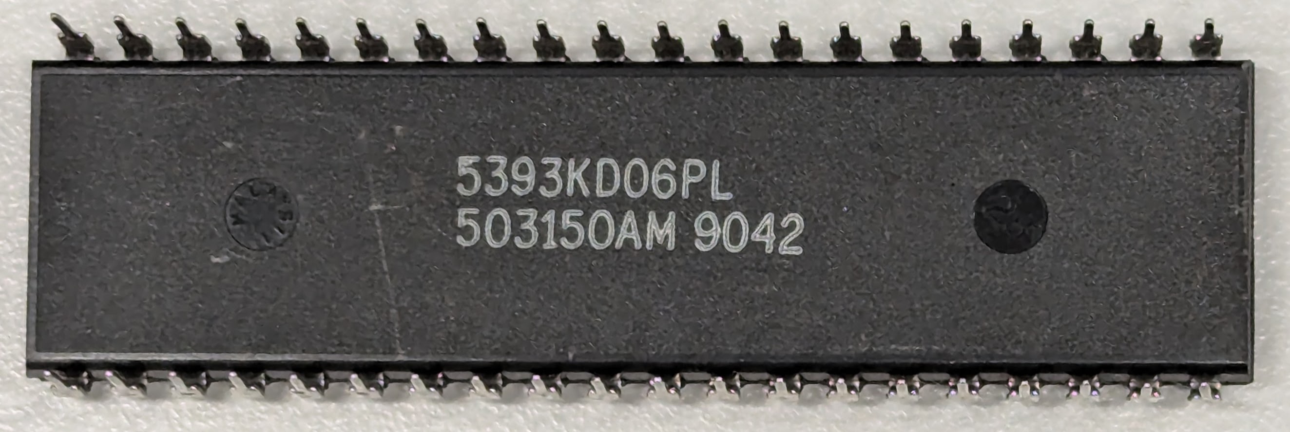
DIP-40 or PLCC-44 (quad surface mount)
Synchronous SCSI: Maximum 5 MB/sec
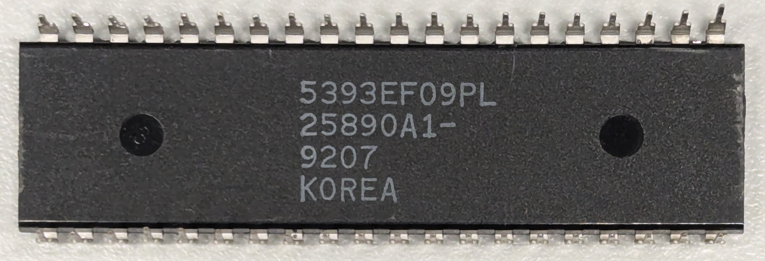
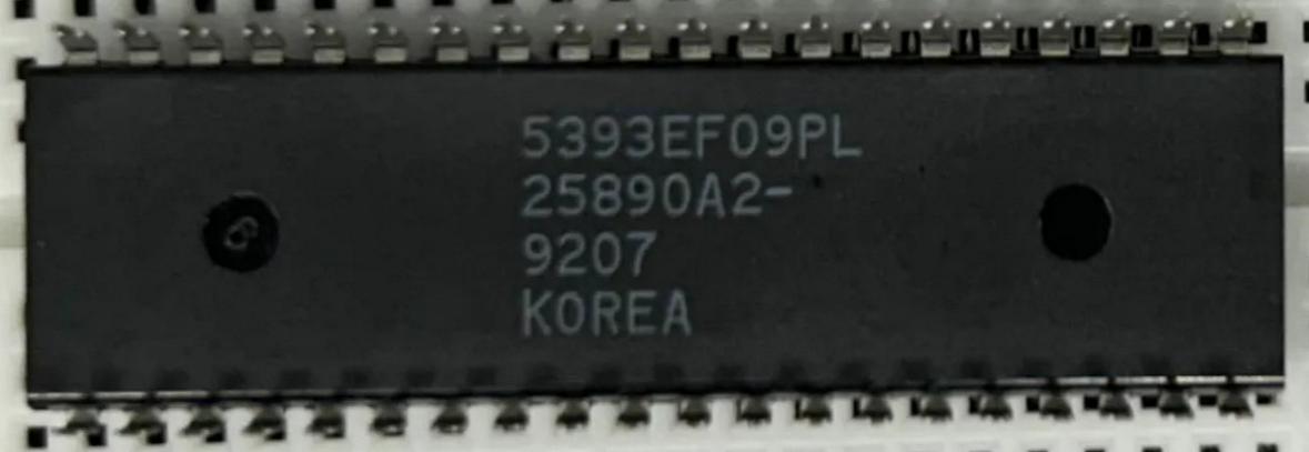
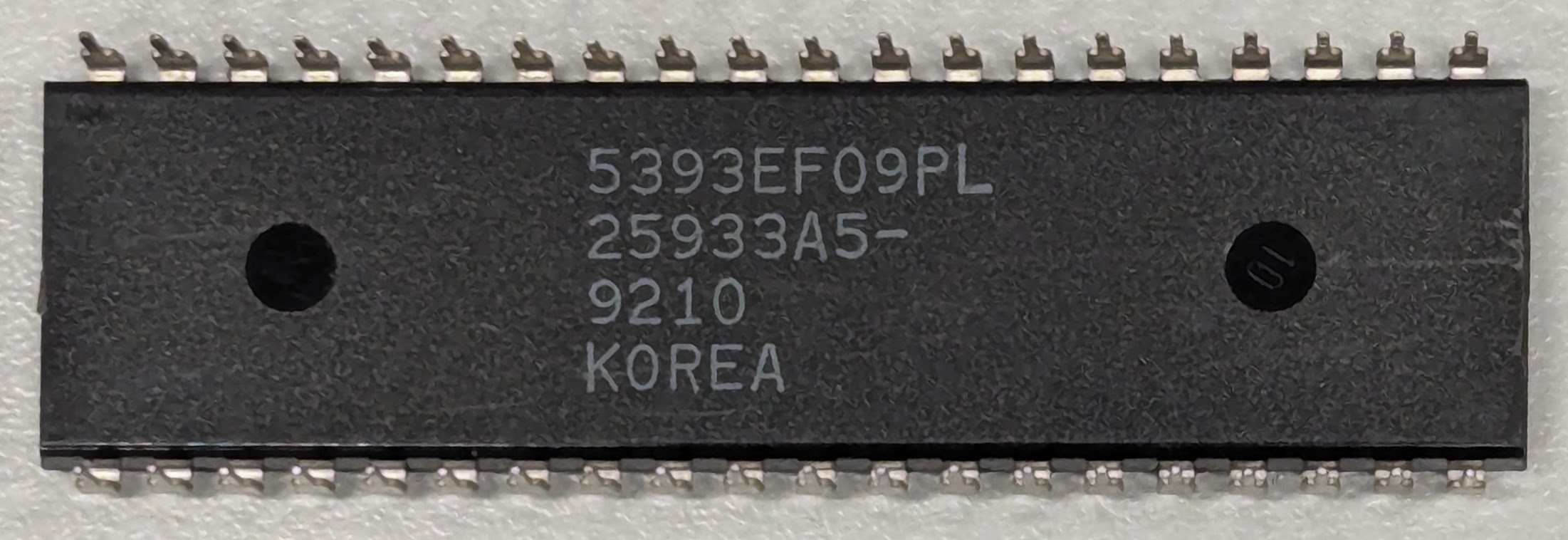
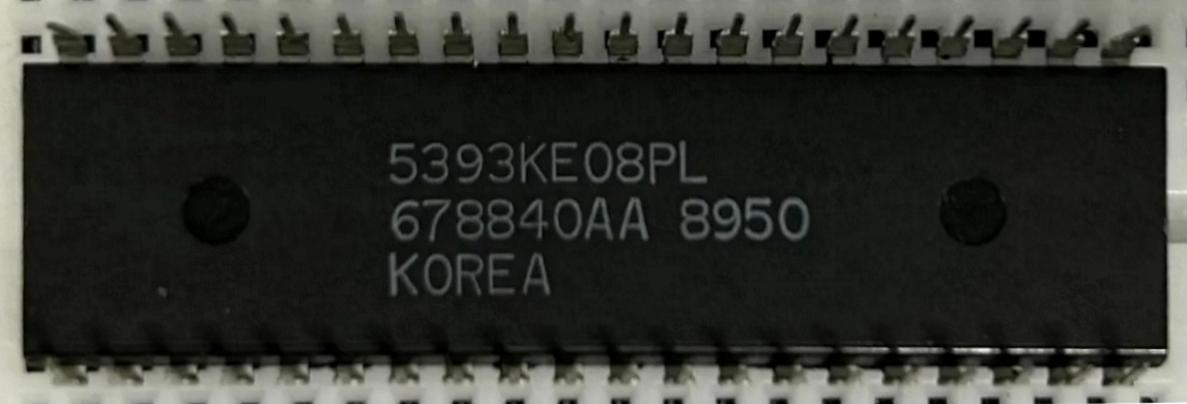
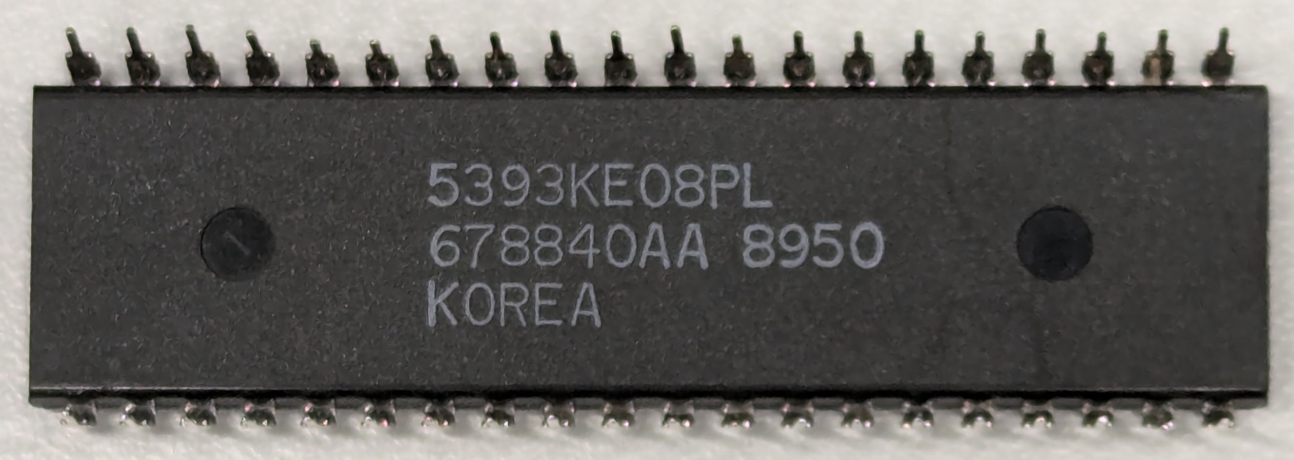
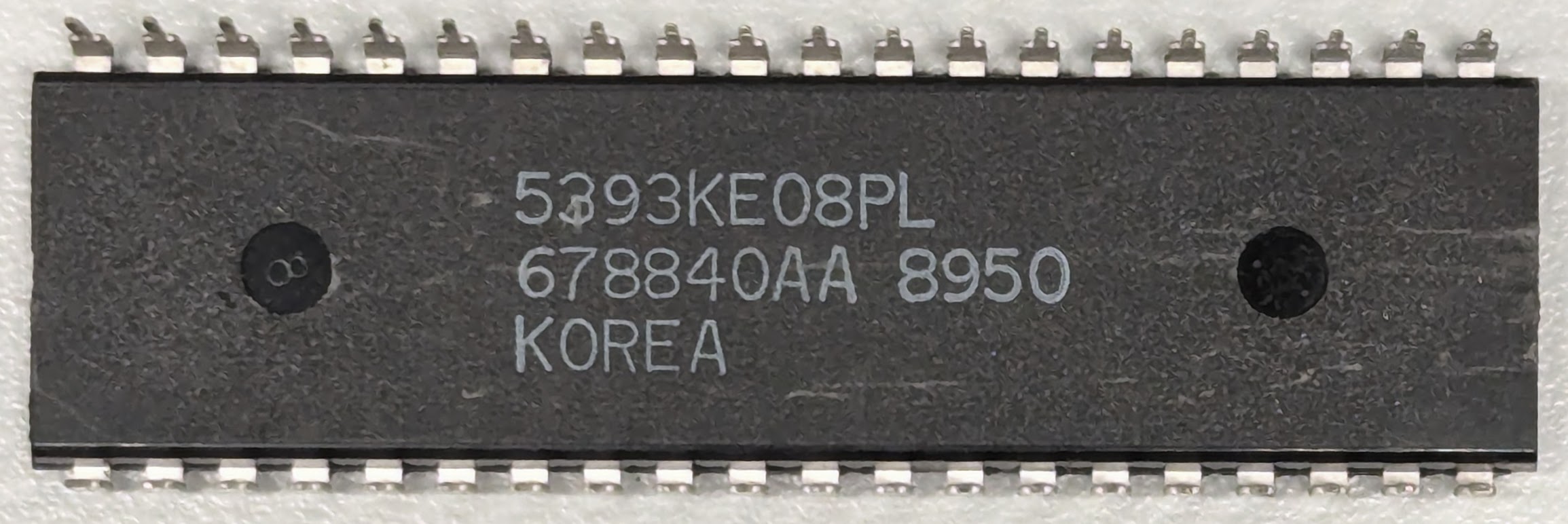
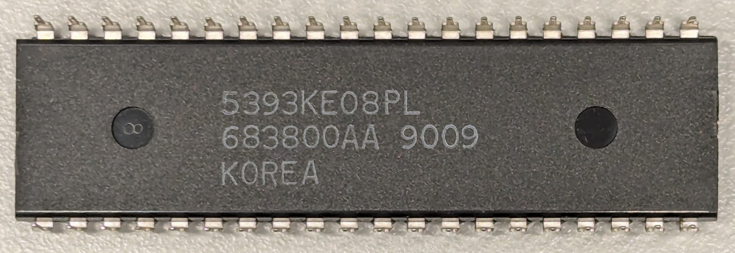
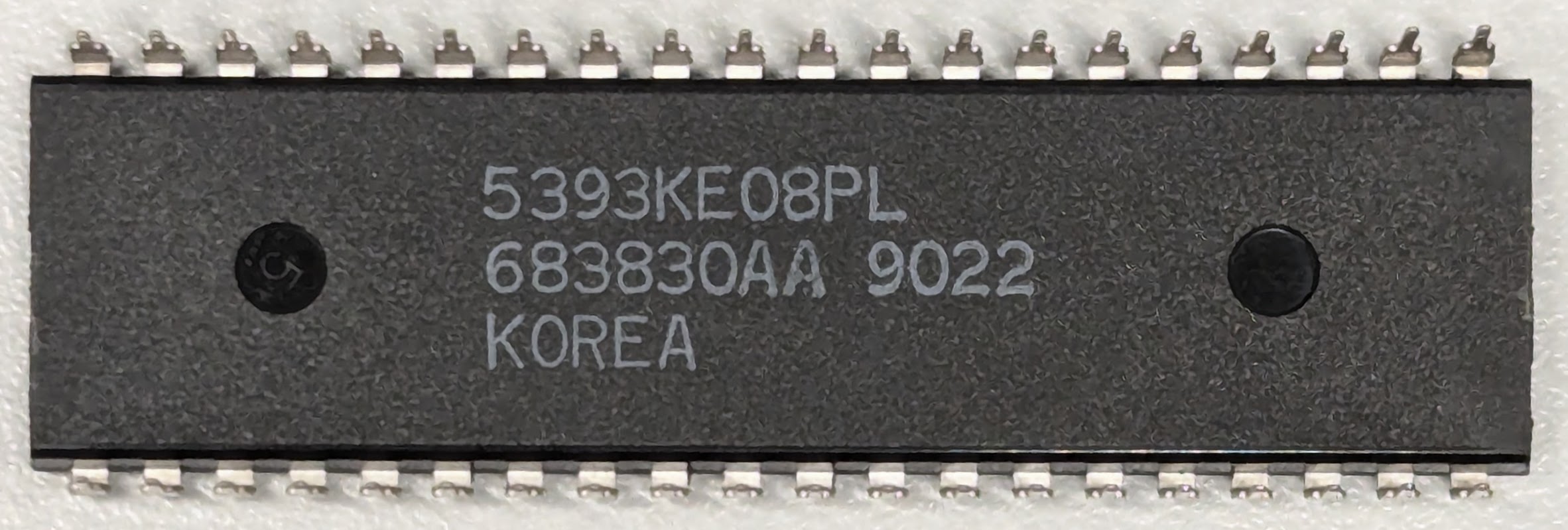
The 5393 code, as seen on the bottom of the ASIC, is the manufacturer code for the WD33C93A product.
Known versions:
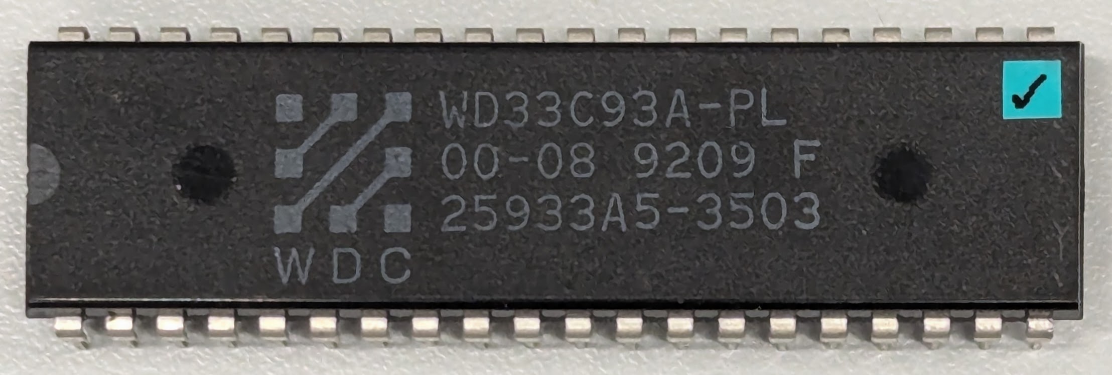
WD33C93A-PL 00-03 - Rev C - Microcode ?06? not software-readable
WD33C93A-PL 00-04 - Rev D - Microcode ?06? not software-readable
WD33C93A-PL 00-06 - Rev E - Microcode 08
WD33C93A-PL 00-08 - Rev F - Microcode 09 - final production
Known production: 8809 9040 9018 9109 9205 9209






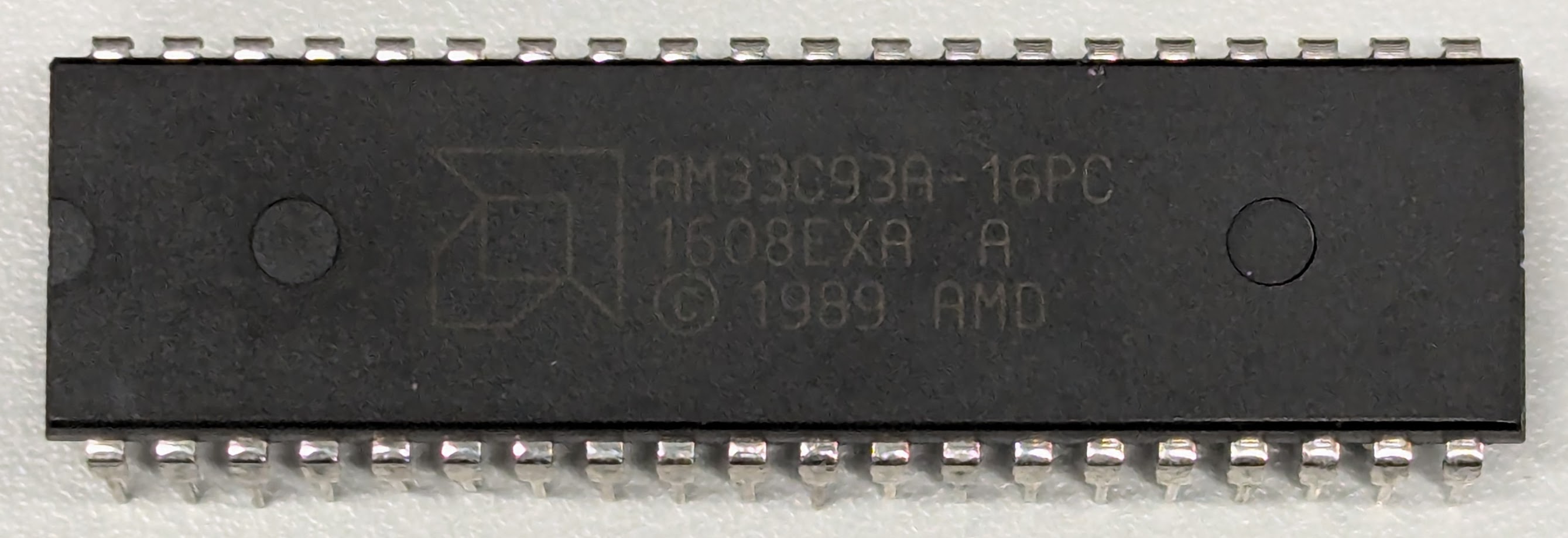
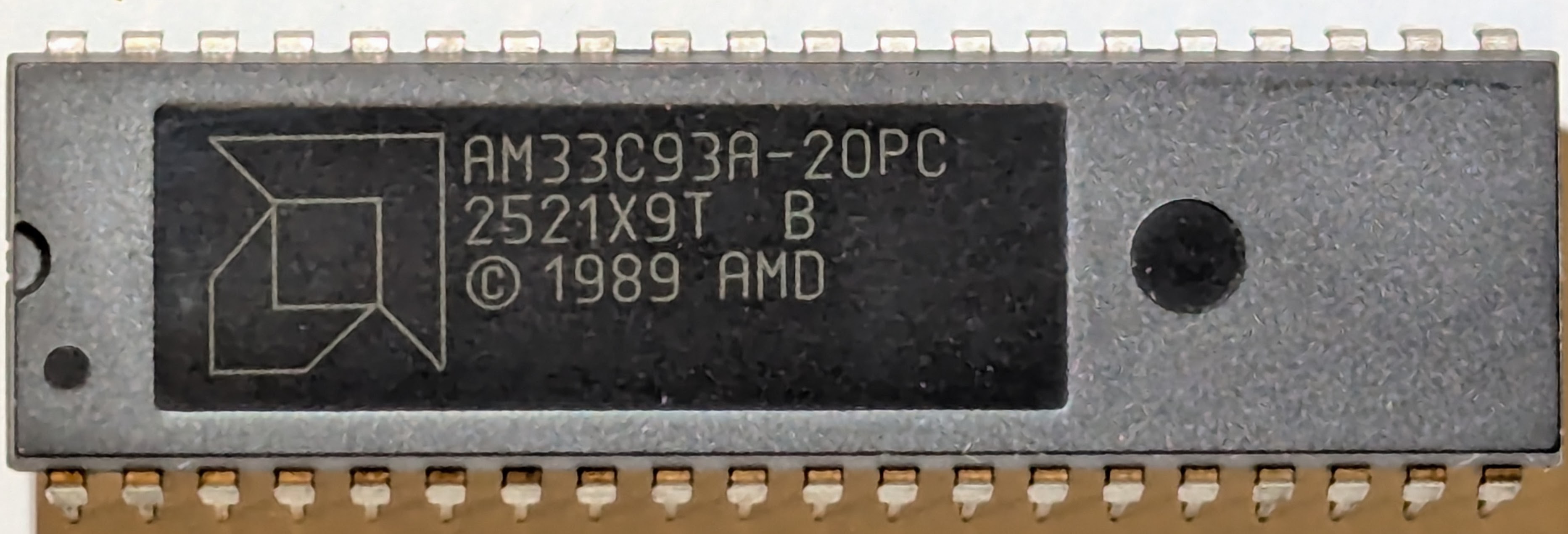
AMD AM33C93A
DIP-40 or 44-pin chip carrier
Synchronous SCSI: Maximum 5 MB/sec
Compatible with WD33C93A; probably the same mask.
Most likely provided as a second-source for WD33C93A.
Known versions:
AM33C93A 8944ES - Microcode ?06?, not software-readable, ENG. SAMPLE
AM33C93A 1048EXA - Microcode 08
AM33C93A 1608EXA - Microcode 08
AM33C93A 2521X9T - Microcode 09
Known production: 8950 9009 9022





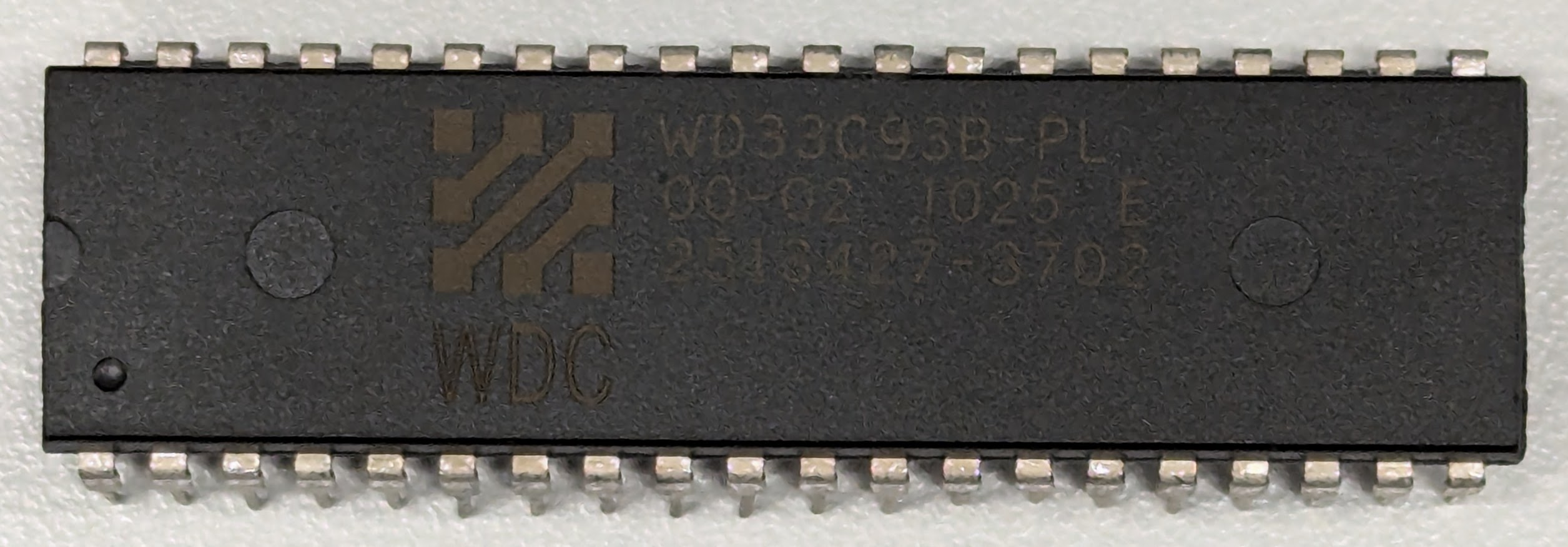
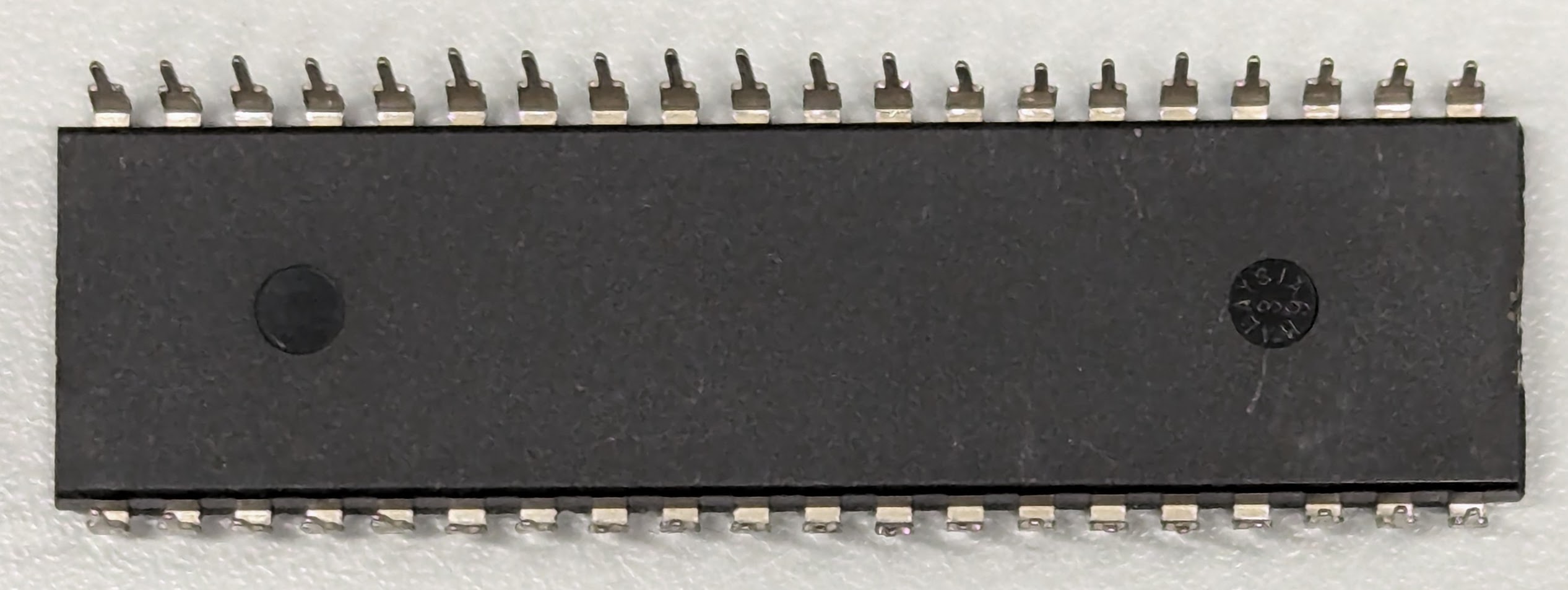
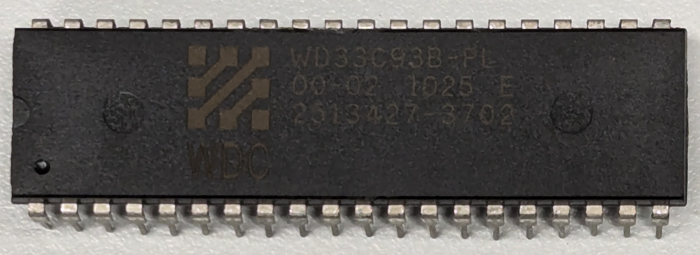
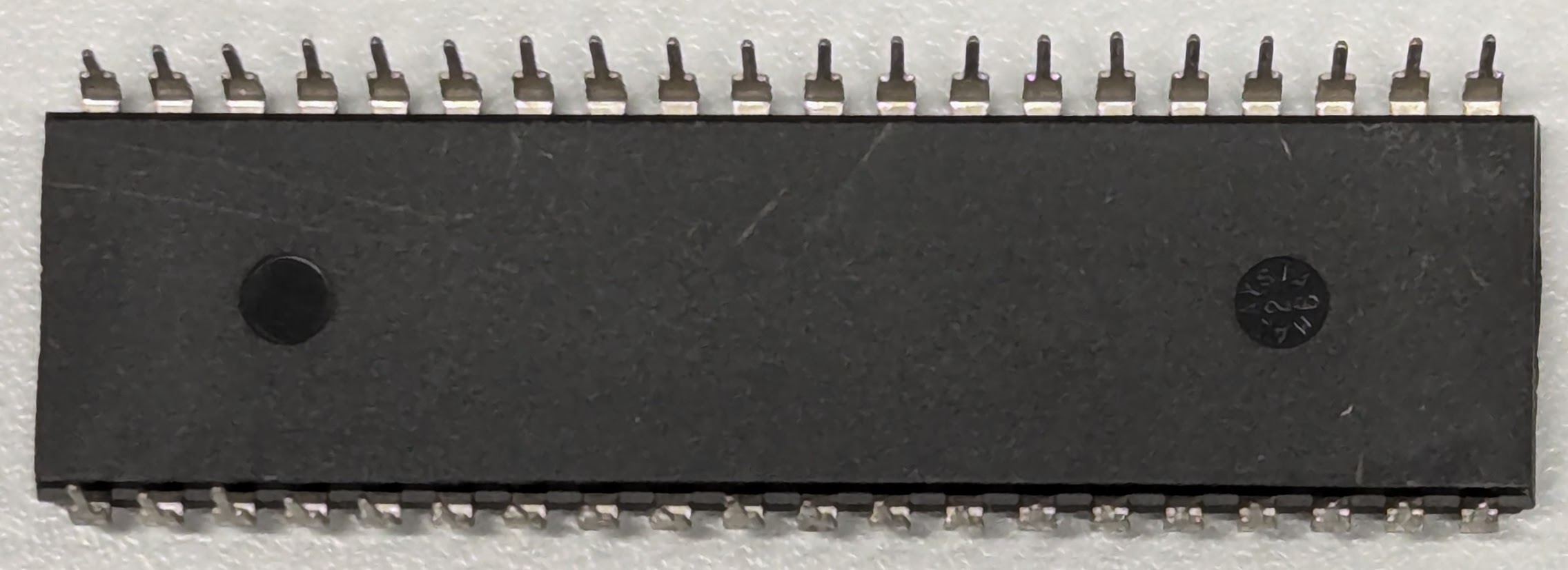
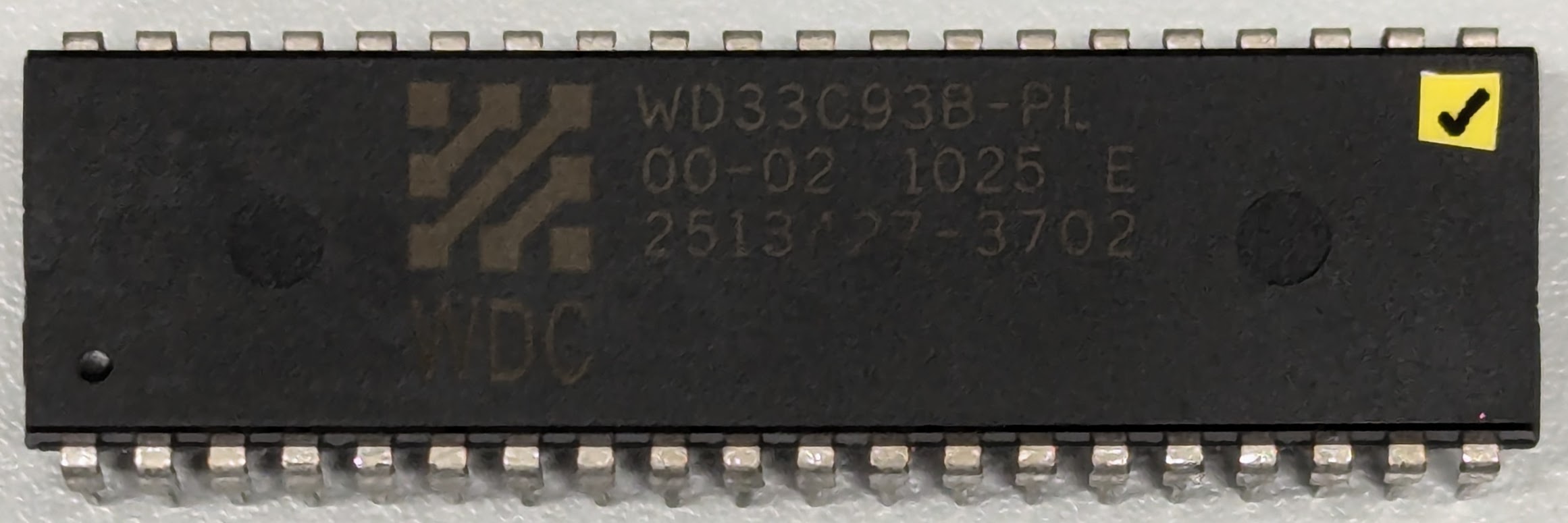
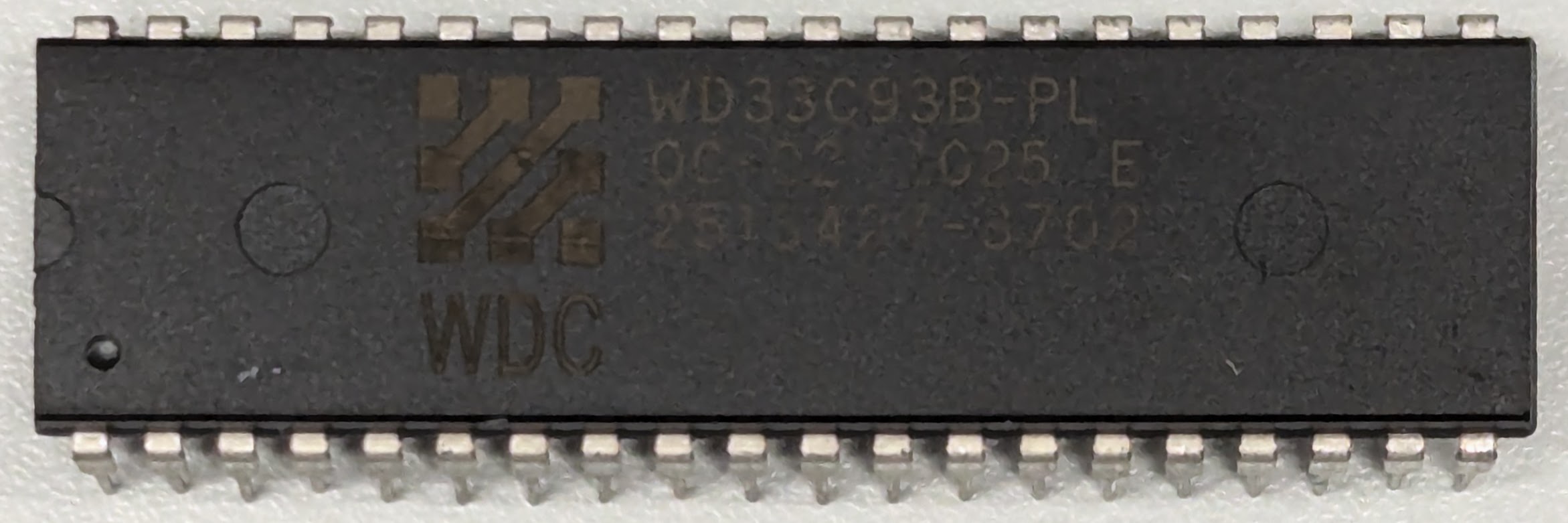
Western Digital WD33C93B
DIP-40 or 44-pin chip carrier
Synchronous SCSI-2: Maximum 10 MB/sec
Backward-compatible with WD33C93A and WD33C93.
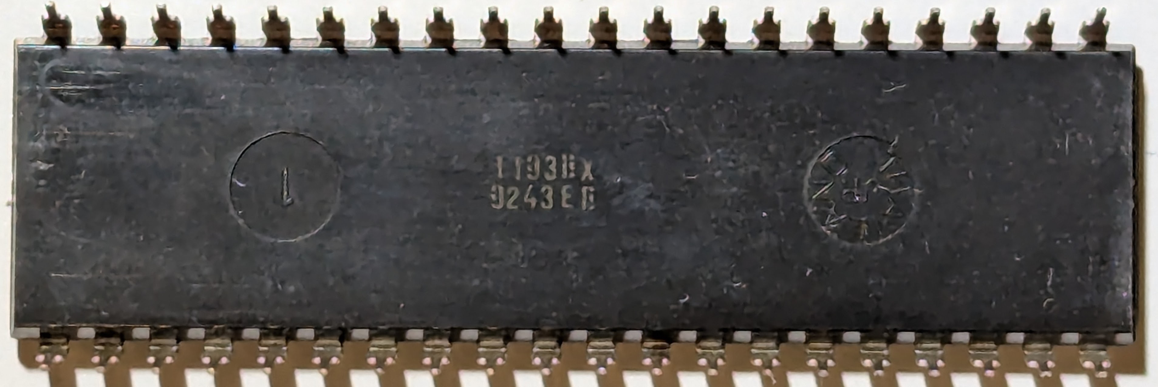
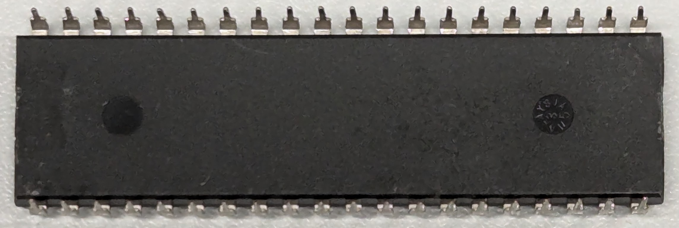
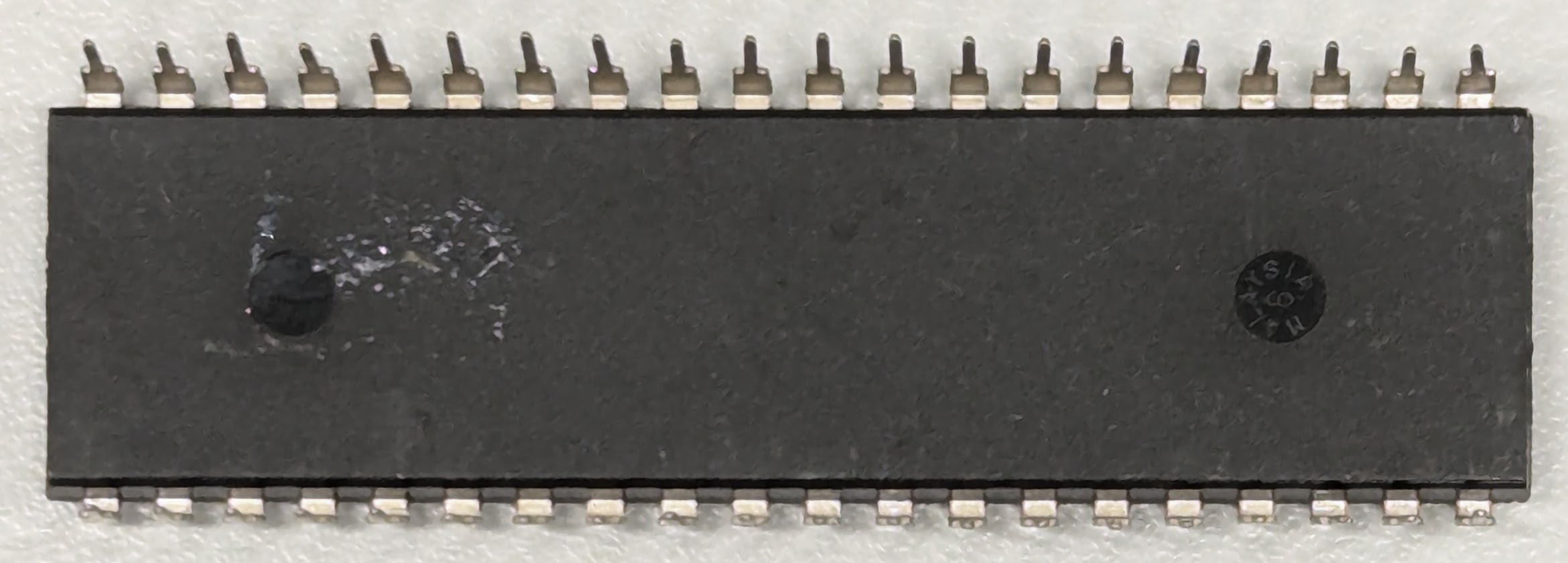
Although not present on the bottom of the ASIC package, the manufacturer code for the WD33C93B is 7393.
Known versions:
WD33C93B-PL 00-02 - Rev E - Microcode 0d
Known production: ?1025?

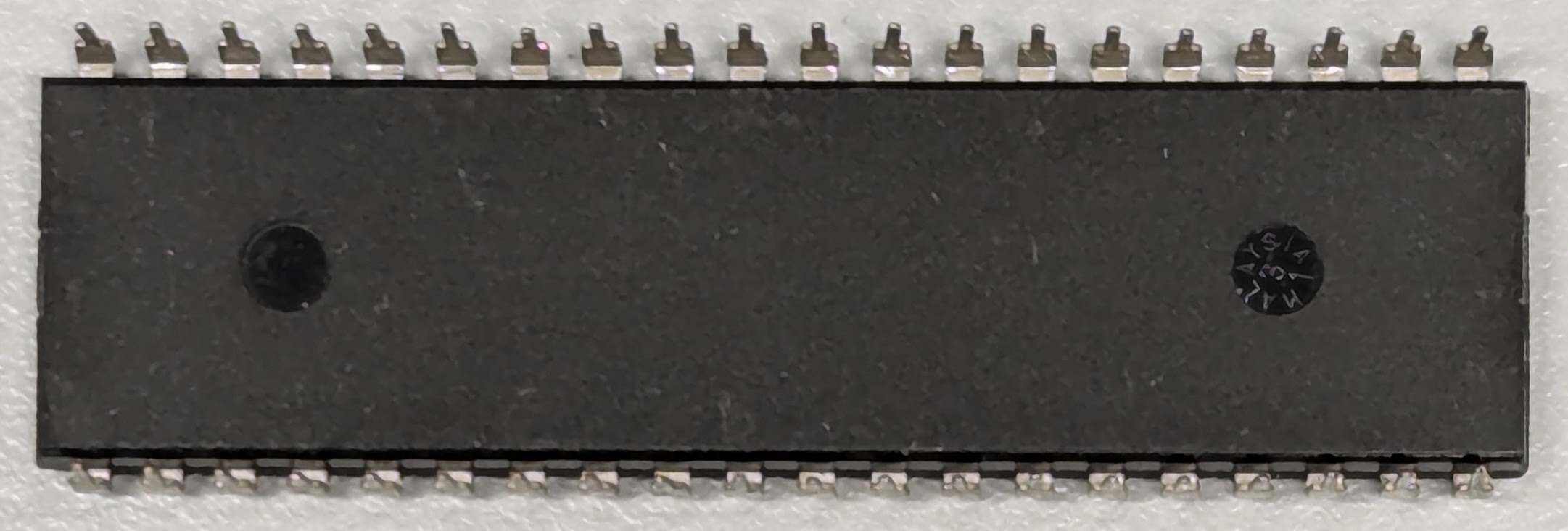
Adaptec AIC-33C93B
DIP-40 or 44-pin chip carrier
Synchronous SCSI-2: Maximum 10 MB/sec
Compatible with WD33C93B; probably the same mask.
Most likely provided as a second-source for WD33C93B.
It uses the same Microcode 0d as the WD33C93B. These parts are fairly rare.
All three of the parts that I've tested do work in synchronous mode in the Amiga 3000. They all hang during access.

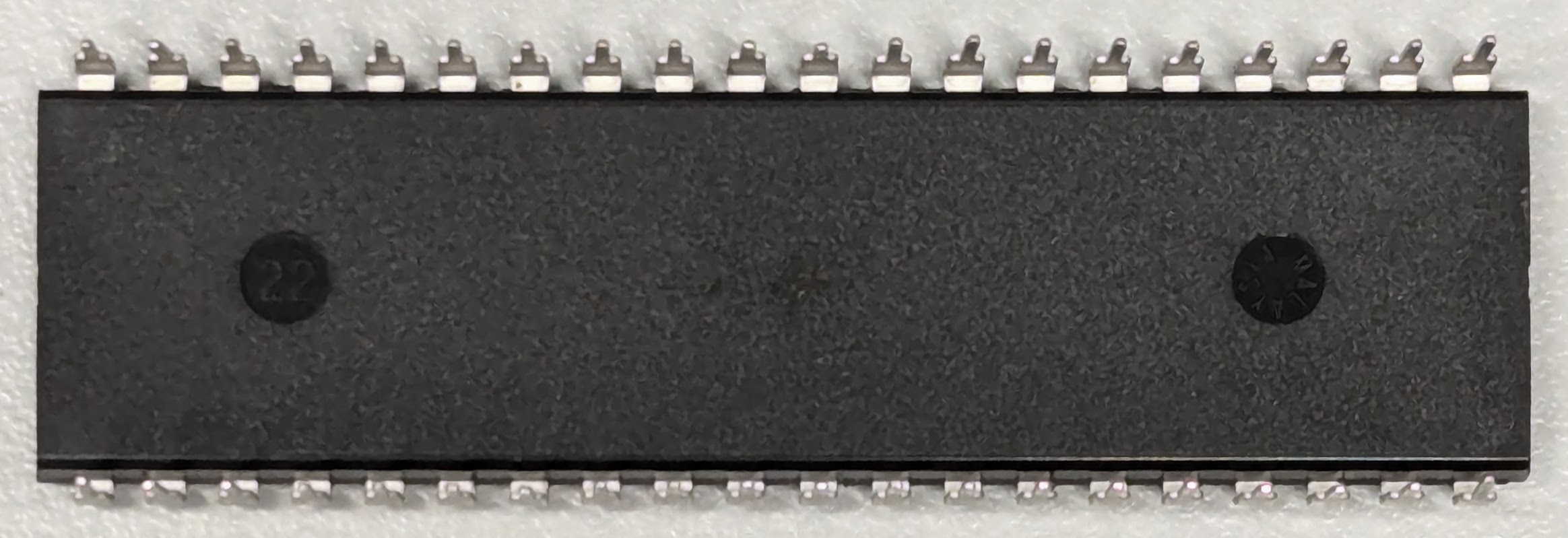
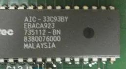
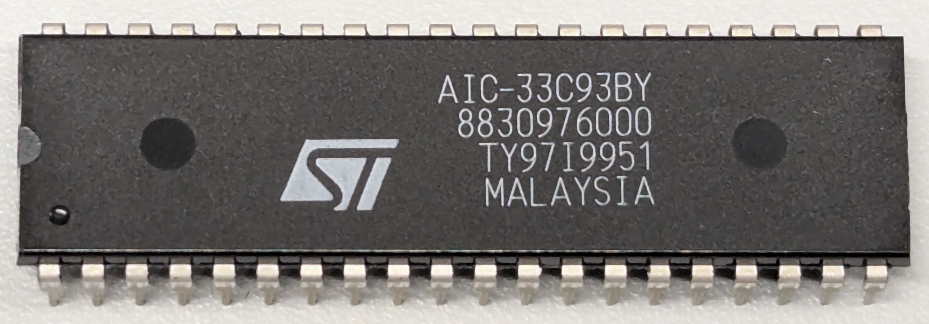
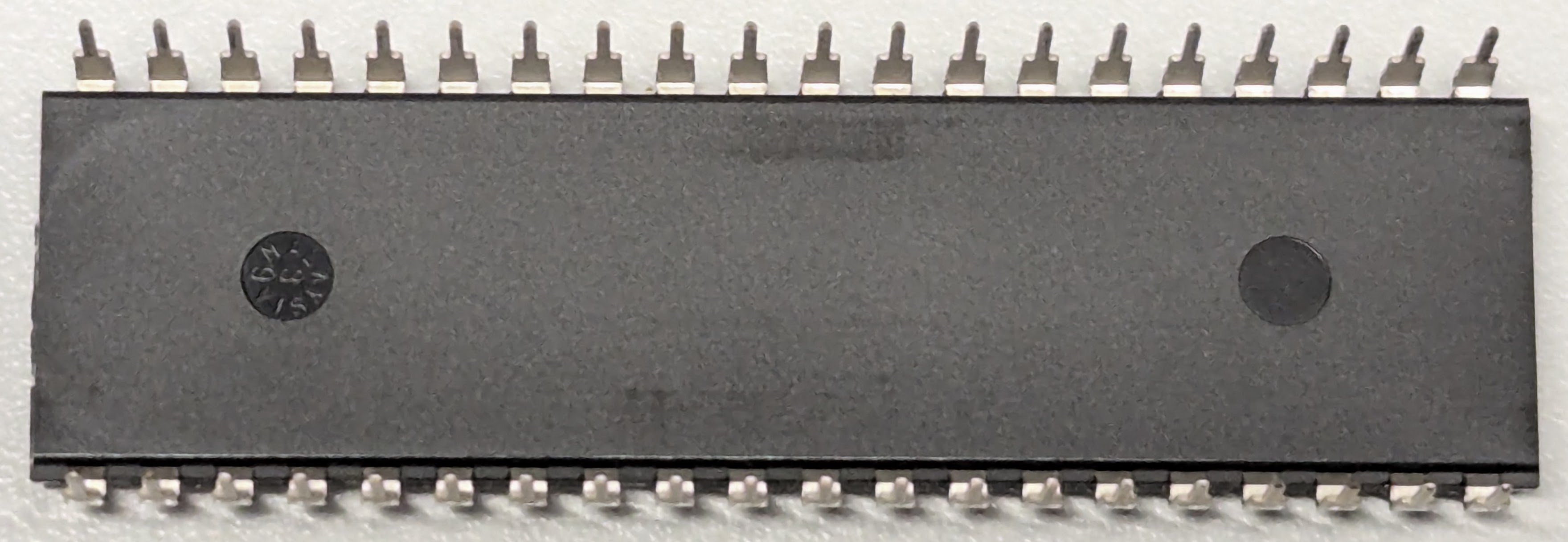
Re-labeled parts
It has become quite common when buying ICs online that vendors will
sand, paint, and relabel ICs in order to provide multiple parts
which look new. This has unfortunately led to less scrupulous vendors
re-labeling mostly-compatible or even broken parts as others
to extract more money from customers.
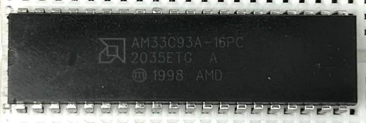
This part labeled AM33C93A is actually a re-marked WD33C93B.
One tell is the 1998 next to the registration mark. Another is that the bottom of the package doesn't have marking consistent with the AM33C93A parts as seen above (it's blank).
Use in the Amiga
The A590, A2091, and A3000 onboard SCSI are compatible with all of the above SCSI chips. The WD33C93 is not recommended for any of them as there are many bugs in that chip. The WD33C93A 00-04 is the minimum, but it still has lockup bugs with some SCSI targets, including CD-ROM and tape drives. WD33C93A 00-06 is less common, but seems to have less issues with SCSI lockups. WD33C93A 00-08 is generally recommended for the Amiga. AM33C93A is a good substitute, though it having the same firmware as the WD33C93A 00-06, it may not be as good as the WD33C93A 00-08. Documentation of differences between WD and AMD chips is not available on the Internet. The best of the series is the WD33C93B, but the Amiga scsi.device does not support the new SCSI-2 10 MB/sec mode of that chip.
Even if it did, you would need a higher frequency base clock to the chip (preferably 20 MHz) and active SCSI termination, so I can understand why they never chose to support it. Too bad as that would probably push the A3000 SCSI up to about 6 MB/sec. It wouldn't make a difference in the case of A590 and A2091. You are limited there by the Zorro II bus speed limit of 3.5 MB/sec.
Overclocking and SCSI
In the Amiga, the un-modified 7.0 ROM scsi.device in the A590 and A2091 sets the WD33C93A to divide the 7 MHz input clock by 2 (see MHz note below). This results in a maximum SCSI clock of ~3.5 MHz.
There is a 14 MHz MOD for these boards which allows the SCSI controller to run faster by doubling the input clock. The scsi driver in ROM needs to change to accommodate this, since dividing by 2 would otherwise then run the SCSI-1 bus at ~7 MHz. The change sets the divisor to be 3, creating a maximum SCSI clock of ~4.7 MB/sec. This is a nice boost, and gets these devices to about 3.5 MB/sec on the Zorro bus (Zorro II maximum).
Certain versions of the WD33C93A and AM33C93A can run at 20 MHz. With even more hardware changes and a different ROM, you can do this Mod to run the SCSI bus at a full 5 MHz. I don't personally recommend this for the A2091 or A590 because the upside is still capped by the Zorro bus. The following article explains how to modify the A590 for both 14 MHz and 20 MHz:
A590 20Mhz mod
Stefan Reinauer has released an amazing turbo board as a drop-in replacement for the WD33C93A in the Amiga and other computers.
The board contains an onboard 20 MHz clock and also has an option to provide active SCSI termination.
It's ideal for the Amiga 3000 onboard SCSI controller when coupled with a ZuluSCSI RP2040 or SCSI2SD v6.
Check out Stefan's Github page for the WD33C93 Turbo board here: https://github.com/reinauer/wd33c93
MHz
The 7 MHz and 14 MHz terms above are simplifications of the actual clocks in Amiga computers.
The 7 MHz clock is actually 7.16 MHz (NTSC) and 7.09 MHz (PAL).
The 14 MHz clock is actually 14.32 MHz (NTSC) and 14.18 MHz (PAL).
The above clocks are derived from the Amiga system video clocks, 28.63636 (NTSC), and 28.37516 (PAL), divding by either 2 or 4.
Undocumented stuff
The WD33C93B firmware implements a few undocumented commands which are not present in the WD33C93A. Most of these perform an unknown operation and then set the SCSI Status register to the issued command code or'd with 0x10.
| WDC_CMD | Command | Description |
|---|
| 0x41 | Unknown | SCSI STATUS is 0x51. No other register is changed. |
| 0x42 | Test Pattern | SCSI STATUS is 0xA2. Sets alternating 0x55 and 0xAA pattern across most registers. It probably implements a register test of some sort. |
| 0x43 | Halt | Unknown actual usage -- the SBIC seems to remain stuck in a busy state and does not respond to further commands. This is probably something like a "halt and tri-state" command. All registers read back as 0xFF (probably timeout) until reset. |
| 0x44 | Register Read | SCSI STATUS is 0x54. Register to read must be set beforehand in CDB1 (0x03). Value read is stored in CDB2 (0x04) by microcode. |
| 0x45 | Register Write | SCSI STATUS is 0x55. Register to write must be set beforehand in CDB1 (0x03). Value to write must be set beforehand in CDB2 (0x04). |
| 0x46 | Unknown | SCSI STATUS is 0x56. CDB1 is set to 0x00. No other register is changed. |
| 0x47 | Unknown | SCSI STATUS is 0x57. No other register is changed. |
| 0x48 | Unknown | SCSI STATUS is 0x58. CDB1 is set to 0x00. No other register is changed. |
WD33C93B internal registers
In addition to the standard registers present in the WD33C93A, the WD33C93B also provides backdoor access to some internal registers through the 0x44 Register Read command and 0x45 Register Write command.
| Register | Value | Description |
|---|
| 0x20-0x3F | | Shadows registers 0x00-0x1F |
| 0x40-0x4F | 0xFF | Unknown |
| 0x50 | 0x00 | Live SCSI data pin values D0-D7 |
| 0x51 | 0x00 | Unknown |
| 0x52 | 0xF0 | Unknown |
| 0x53 | 0xFF | SCSI control pins (Bit 0=IO, Bit 1=CD, Bit 2=MSG), negative logic |
| 0x54 | 0xFD or 0xF8 | Unknown |
| 0x55 | 0xF0 or 0xF3 | SCSI control pins and other state (Bit 2 is REQ). Unknown if ATN, BSY, RST, or ACK are reported in any register. |
| 0x56 | 0x00 or 0x80 | Unknown |
| 0x57 | 0x54 | Unknown |
| 0x58 | 0x44 | Unknown |
| 0x59-0x79 | 0xFF | Unknown |
| 0x7A | 0x04 or 0x06 | Unknown |
| 0x7B | 0xAA or 0x00 | Unknown |
| 0x7C | 0x11 or 0x01 | Unknown |
| 0x7D | 0x80 | Unknown |
| 0x7E | 0x7E | Unknown |
| 0x7F | 0x00 | Unknown |
Other links
Amiga
- Various Amiga projects
 This part labeled AM33C93A is actually a re-marked WD33C93B.
One tell is the 1998 next to the registration mark. Another is that the bottom of the package doesn't have marking consistent with the AM33C93A parts as seen above (it's blank).


 This part labeled AM33C93A is actually a re-marked WD33C93B.
One tell is the 1998 next to the registration mark. Another is that the bottom of the package doesn't have marking consistent with the AM33C93A parts as seen above (it's blank).