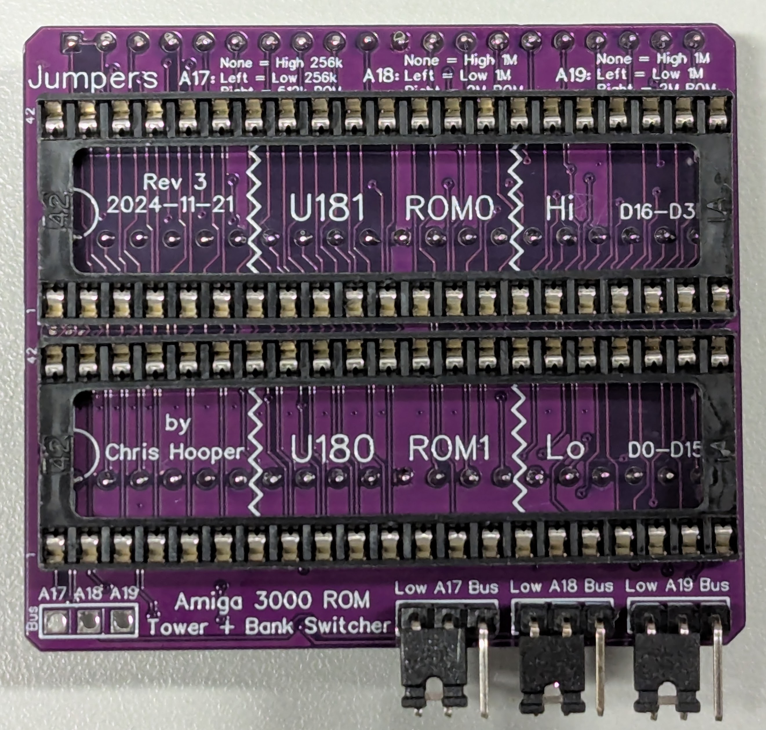
 This is the current revision of the board. Most of the guide below is out of
date, but still relevant to the order and components used to build the latest
version of the Amiga 3000 ROM Tower bank switcher. The major enhancement for the Rev 3 version is that the top side socket positions and spacing is now identical to the U180 and U181 sockets, meaning a Kicksmash32 may be dropped in to the sockets and used.
This is the current revision of the board. Most of the guide below is out of
date, but still relevant to the order and components used to build the latest
version of the Amiga 3000 ROM Tower bank switcher. The major enhancement for the Rev 3 version is that the top side socket positions and spacing is now identical to the U180 and U181 sockets, meaning a Kicksmash32 may be dropped in to the sockets and used.
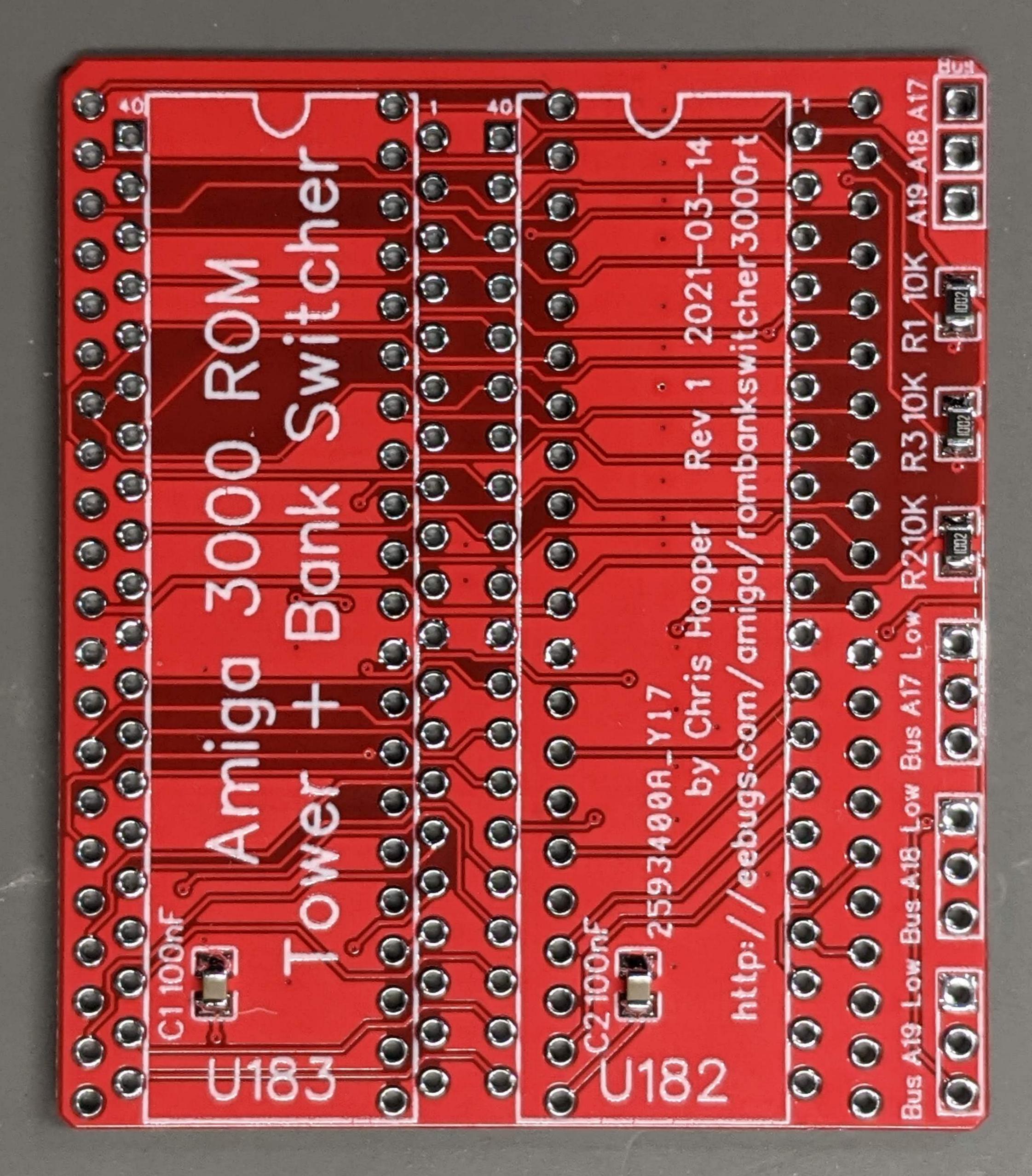
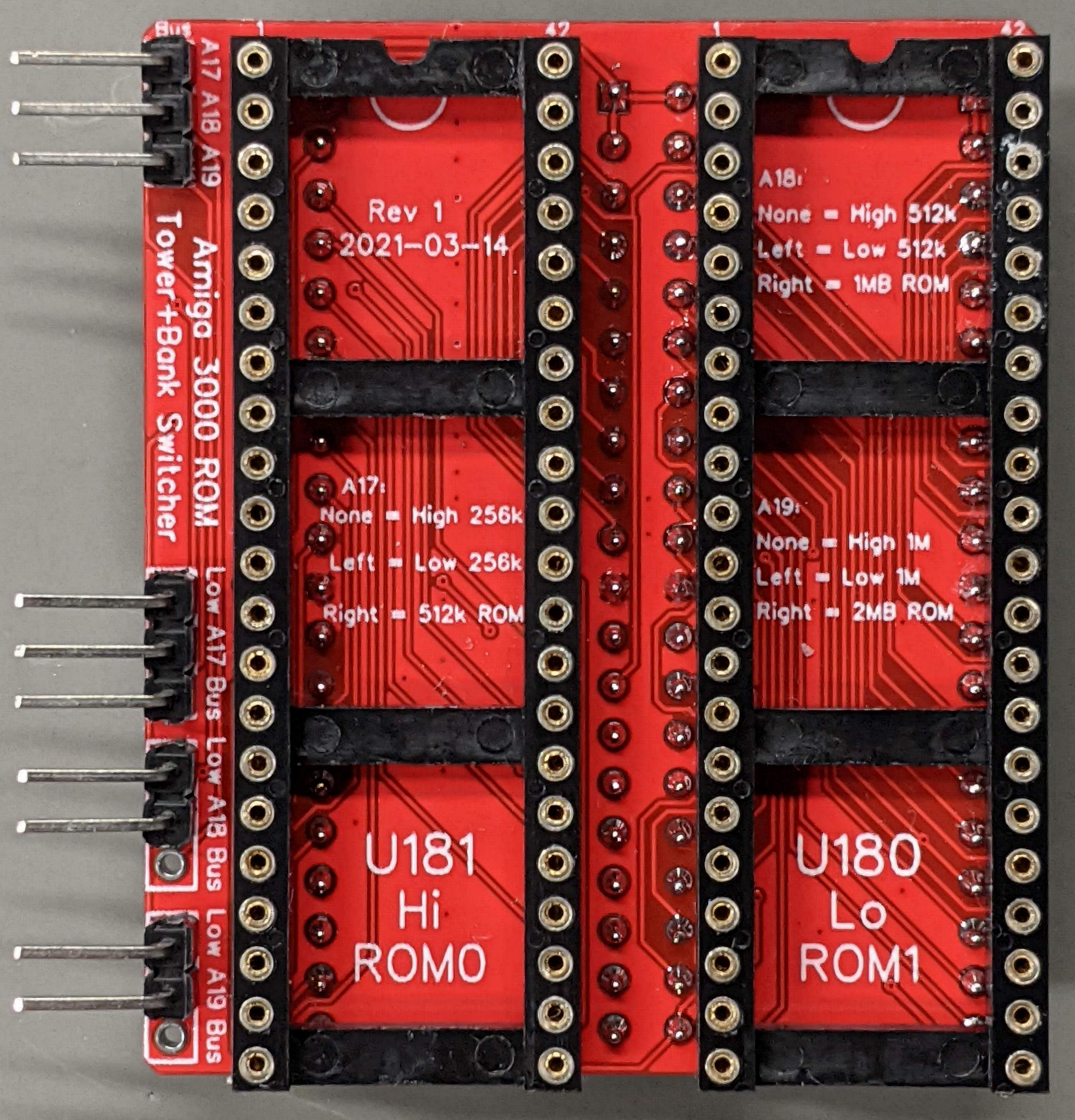
HW Rev 1: 2021-03-14
TLDR: Yes, you can use this board to add standard 27C400 EPROMs, such as those programmed with AmigaOS 3.1.4 or AmigaOS 3.2 in your older revision Amiga 3000 where only the U182/U183 sockets may be used. Yes, it replaces the ROM Tower, which might or might not have come with your Amiga.
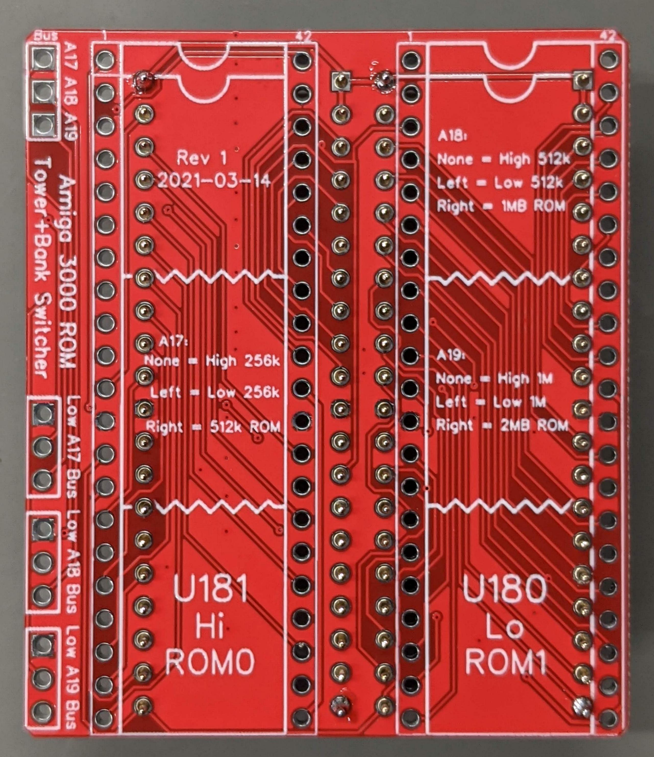
The Amiga 3000 ROM bank switcher (ROM Tower Version) is a simple board which allows the installation of 2x 2MB ROM/EPROM/EEPROM in the Amiga 3000 Kickstart ROM sockets U182 and U183. These sockets only support 256KB Intel 27C220 ROMs (X 2 sockets = 512K Kickstart image), but with this bank switcher, you can use the more common 28F400/28F800/28F160 ROM types which would typically be installed in U180/U181 in newer Amiga motherboards. The ROM Bank Switcher provides jumpers which allow the other space of the ROMs to be used as alternative Kickstart images.
This switcher is designed for the earlier Amiga 3000 motherboards (before 9.x) where the ROM Tower is required for the 27C400 EPROMs to be used. Not all older Amigas came with the ROM Tower. The ROM Bank Switcher can be used in place of the Commodore ROM Tower to allow the same functionality of the ROM Tower.
This ROM bank switcher would probably work with newer Amiga 3000 motherboards as well. Unfortunately, most of them do not have the U182/U183 sockets populated. DO NOT INSTALL THIS BOARD IN U180/U181. It does not work there, and could damage your Amiga and/or your ROMs. If you have a Rev 9.x Amiga motherboard, use the Amiga ROM Bank Switcher 3000 in those sockets.
You may also be interested in the Amiga ROM Bank Switcher board for other Amiga models.
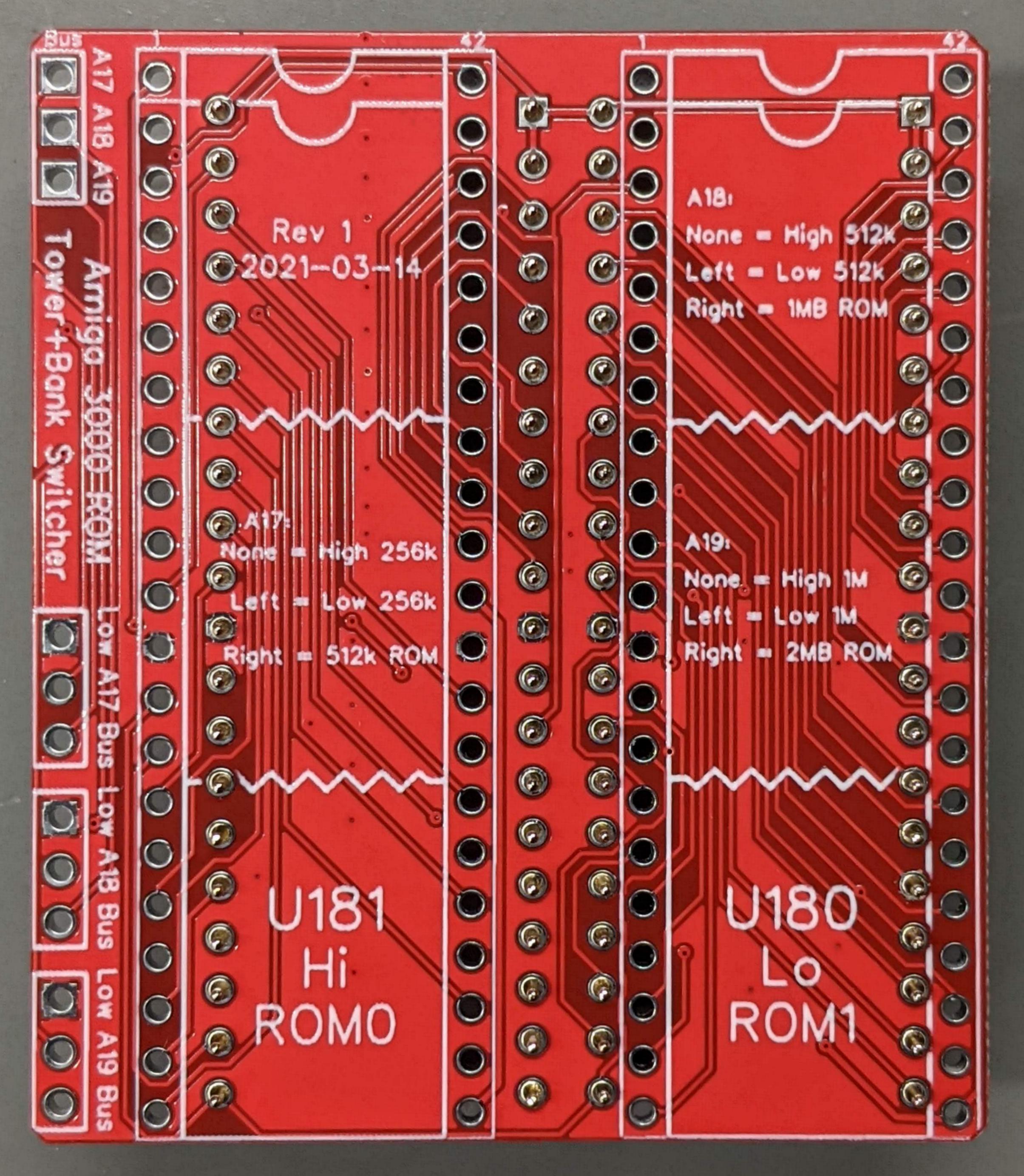
The A17 jumper supports three positions:
Some Amigas (A1200 for example) allow for 1MB ROMs instead of 512K. This is unfortunately not the case for the Amiga 3000. There, the limitation is both the A3000 Gary and also the U182/U183 sockets. The Gary issue can be solved with an enhanvement (Romy -- more on that below). The U182/U183 socket issue is that ROM A17 is not available at those sockets. ROM A17 is needed to address more than a 512KB Kickstart image. So to use, for example, a 1MB Kickstart image, you'll need to connect Bus A17 on the ROM Tower / Bank Switcher to CPU A19 somewhere on the Amiga. Gary is a good choice for this. When using a 1MB image, you'd then set the A17/Bus jumper so that the ROM A17 would be driven by the CPU's A19 signal.
Instead of a switch or switches on the exterior of the computer, another option is to just use two-pin jumpers, placing one each as desired on the A17, A18, and A19 headers. This won't make changing the selected ROM image very easy, but you may only want to use a single ROM image anyway.
The Gerbers are available in Github here: https://github.com/cdhooper/amiga_rombankswitcher_a3000_romtower
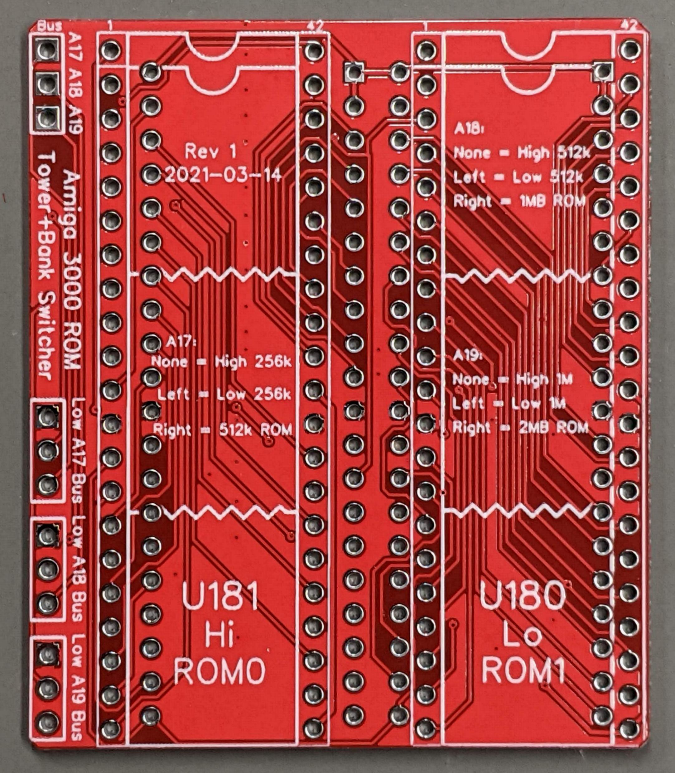
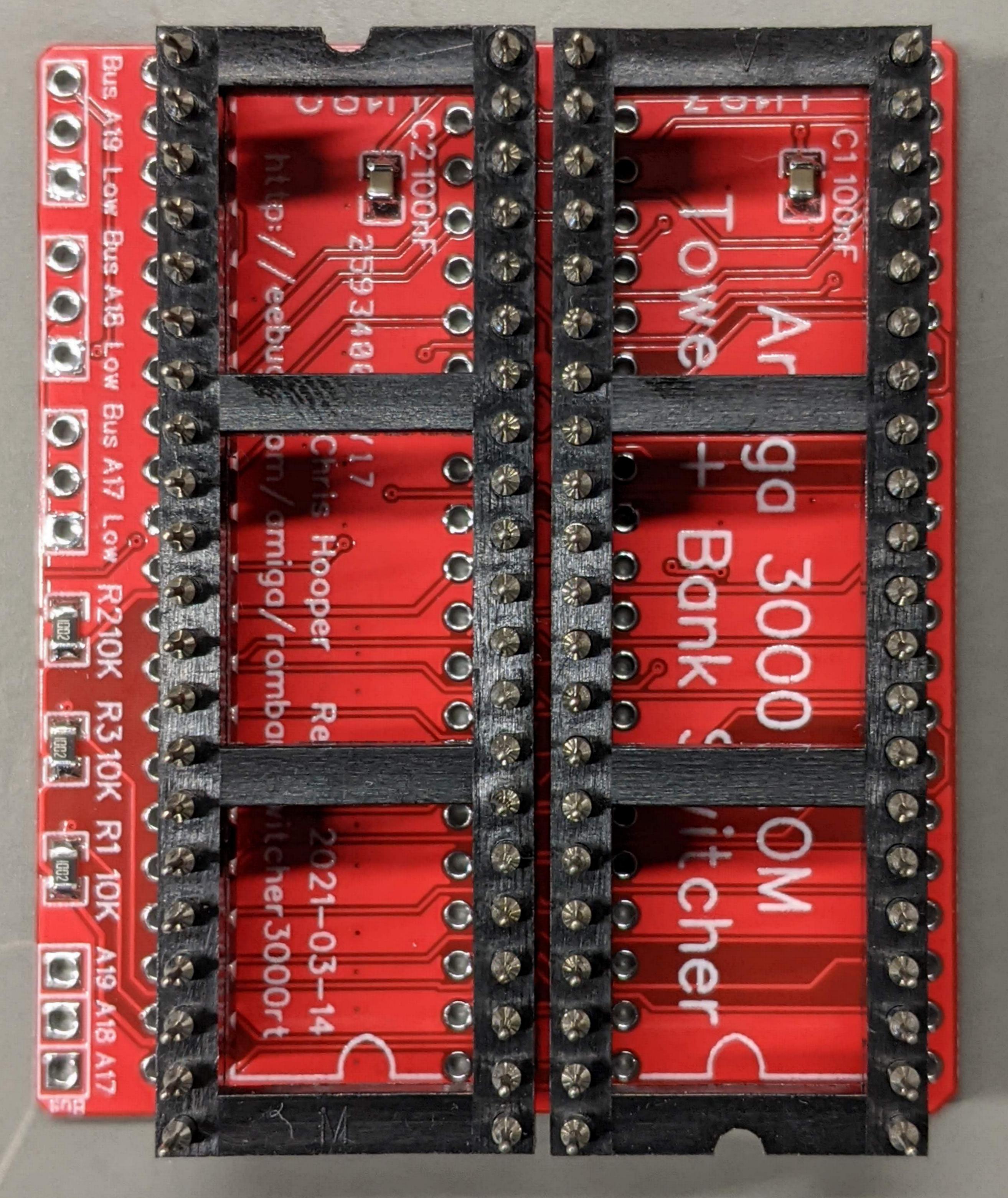
Another view of the same board on the left.
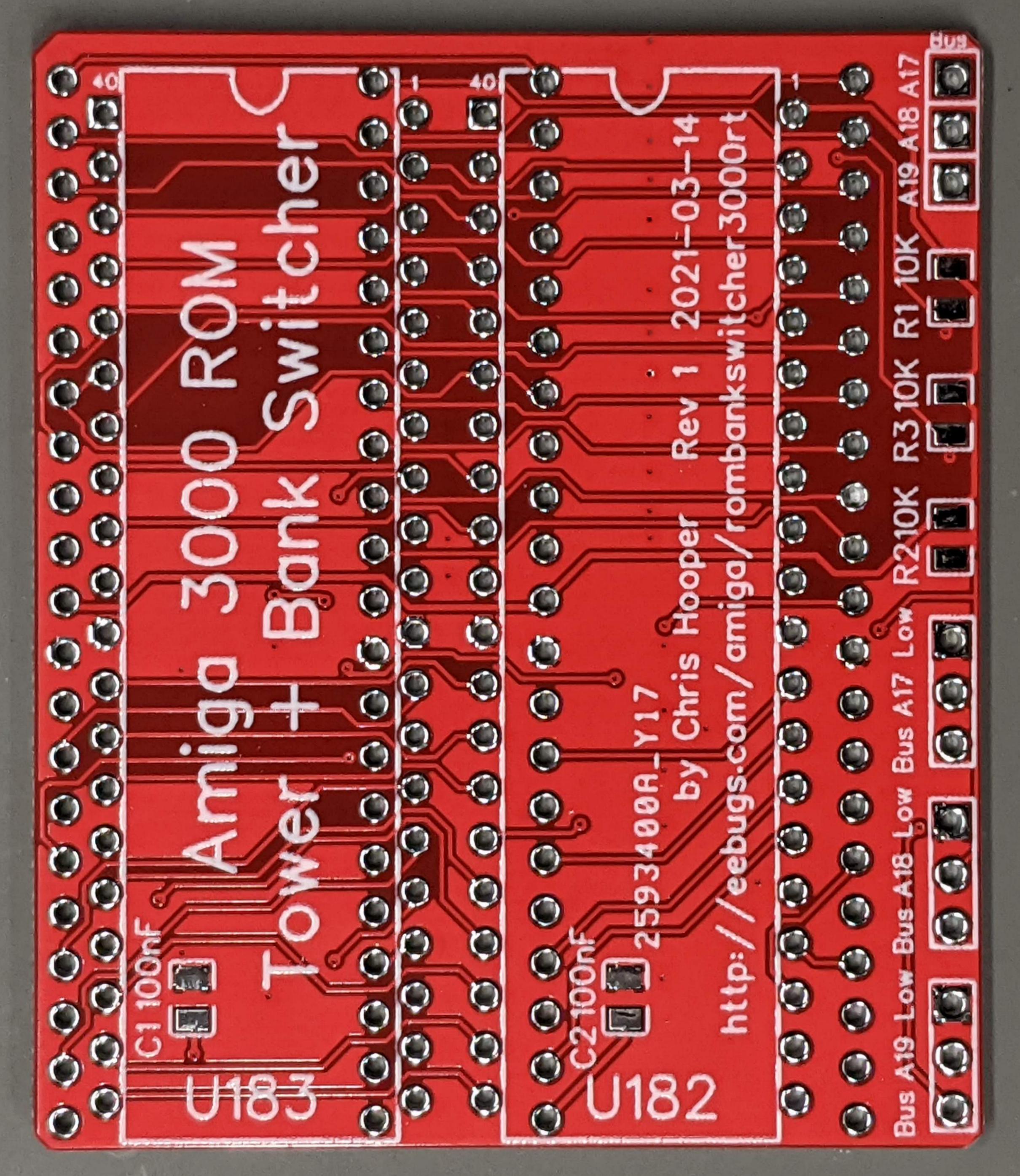
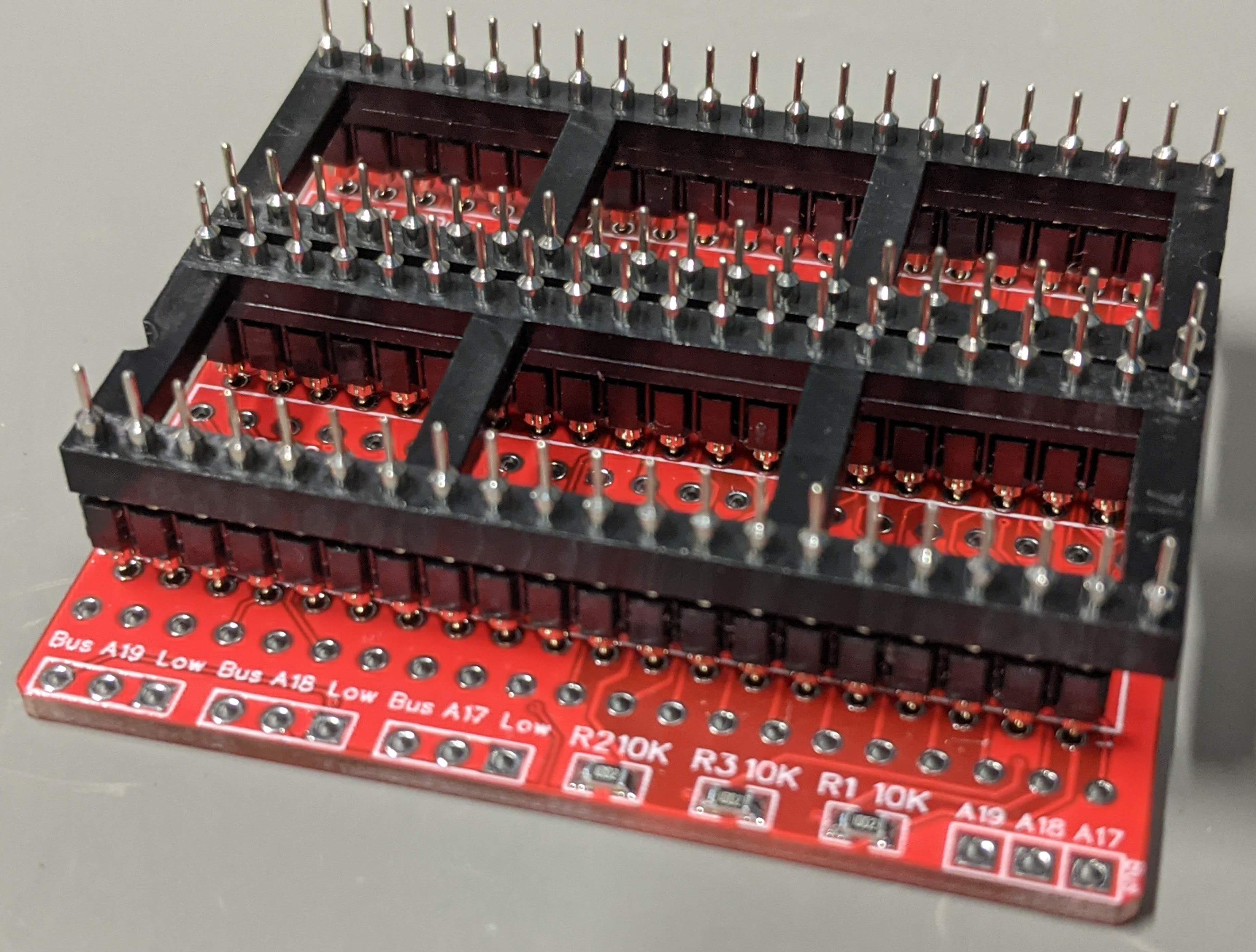
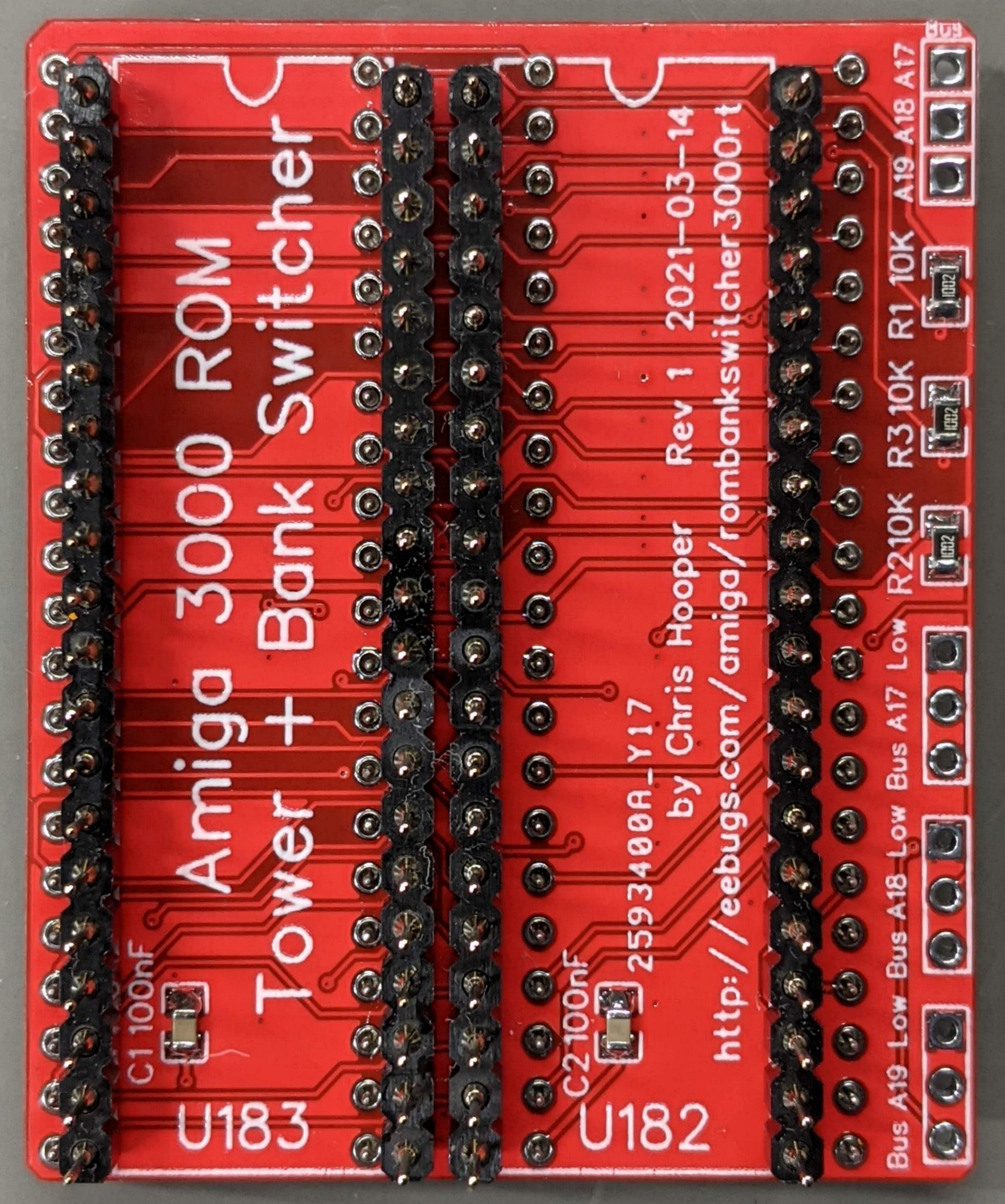
...and a top view of the same board on the right.

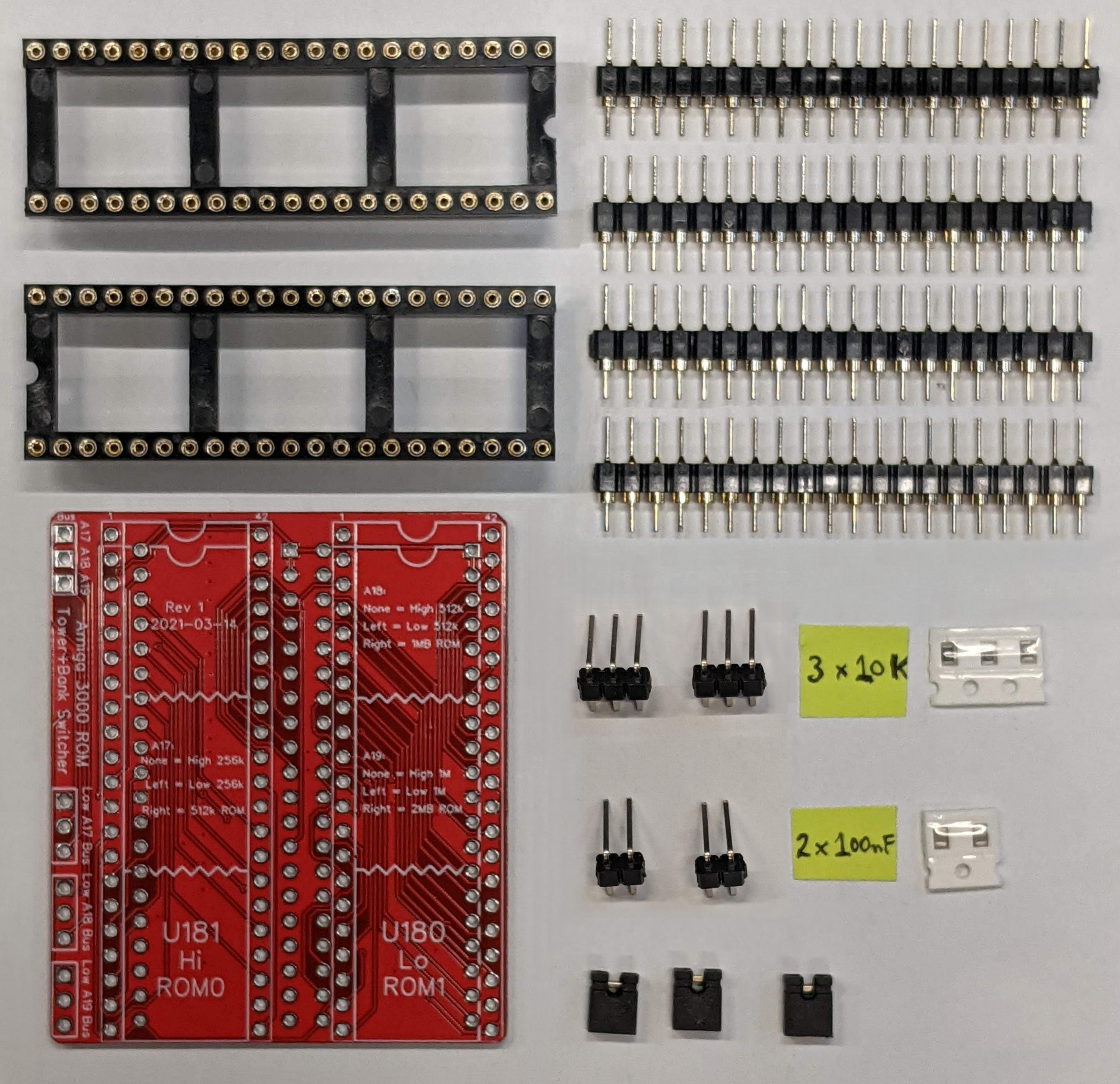
On the left, I've tacked down the corners of the four header sockets. I can then pick up the board and press the headers to the PCB as I heat up the tacked pins. This allows the opportunity to make the headers flush to the PCB.
On the right, the headers have been fully soldered down to the board.
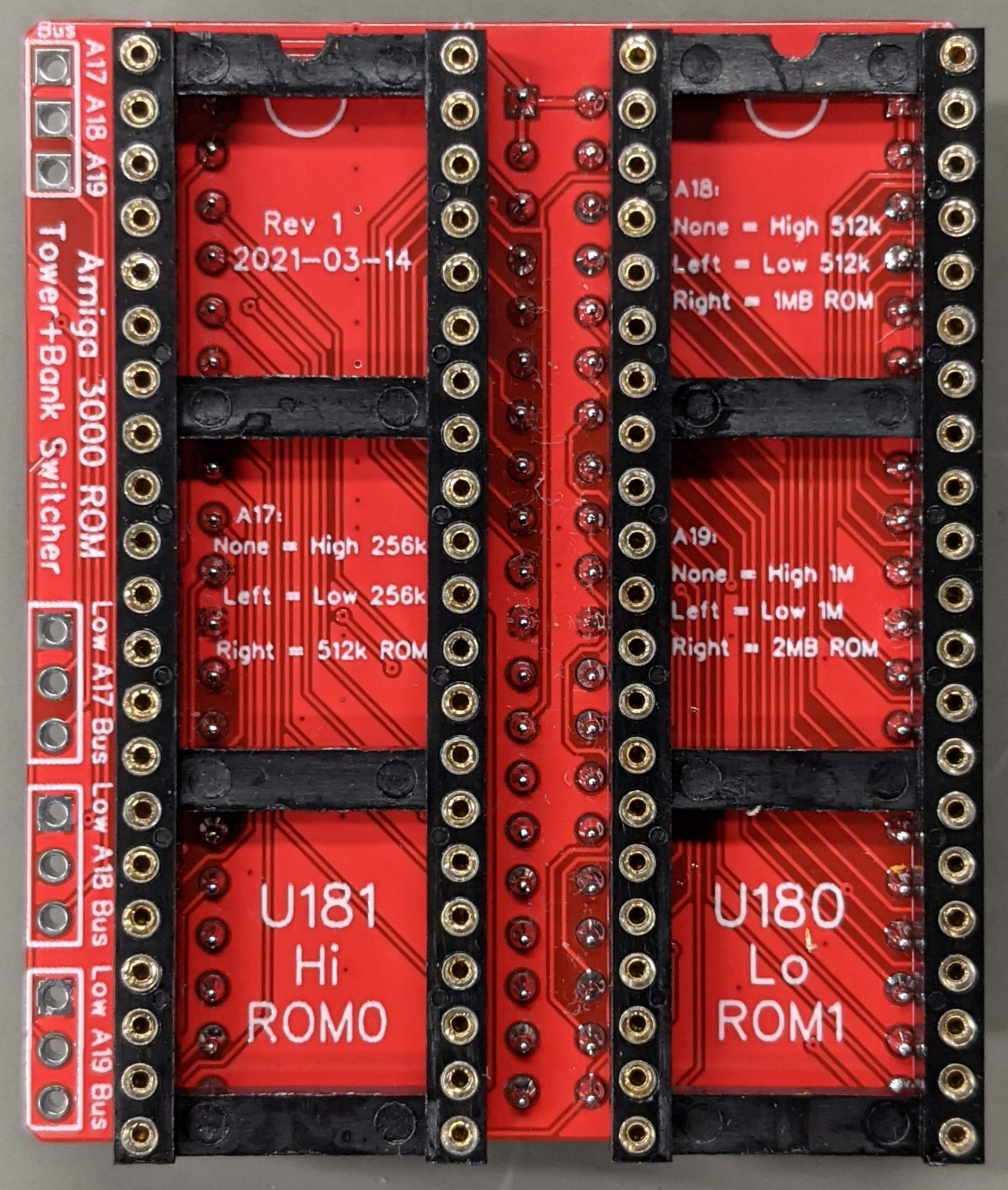
Now remove the sockets from the bottom headers and install them in the top (left).
On the right, these headers have been soldered down.
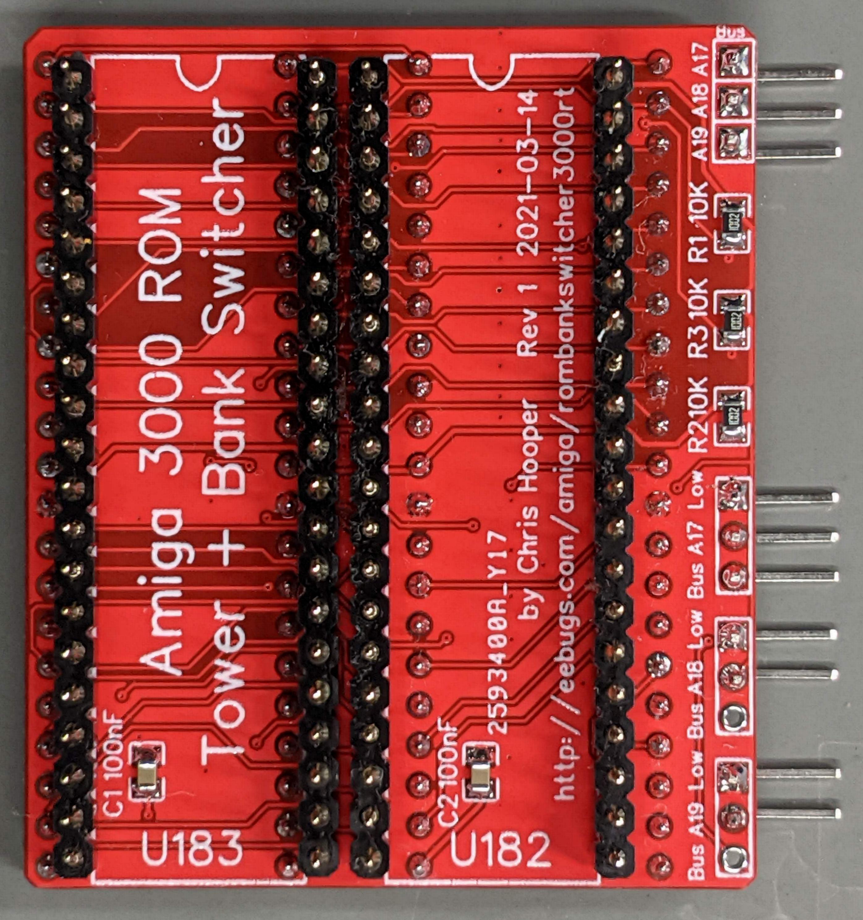
Finally, install the jumper headers. As you see here, I used a three-pin header for Low/17/Bus and two-pin headers for Low/A18 and Low/A19 positions. You could choose to install all 3-pin headers if desired, but as stated above, it's likely you will not use the Bus positions of the header for A18 and A19.
If you plan to use 1MB ROMs, you will need to run a jumper wire from the Bus A17 header (you could also solder it down instead of using a header if this board is going to be permanent in your Amiga). This wire must connect somewhere else on your motherboard where CPU A19 is provided (Gary is a good choice), since it's not available at U182/U183. This is not a mistake. ROM A17 connects to the CPU's A19 signal on the Amiga 3000.
To use 1MB ROMs in your Amiga 3000, you will also need an enhancement to Gary which decodes the second half of the 1MB ROM. Look for the Romy project by SpeedGeek. A much improved version of Romy can be found at https://github.com/reinauer/amiga-romy by Stefan Reinauer.
You are done with assembly.
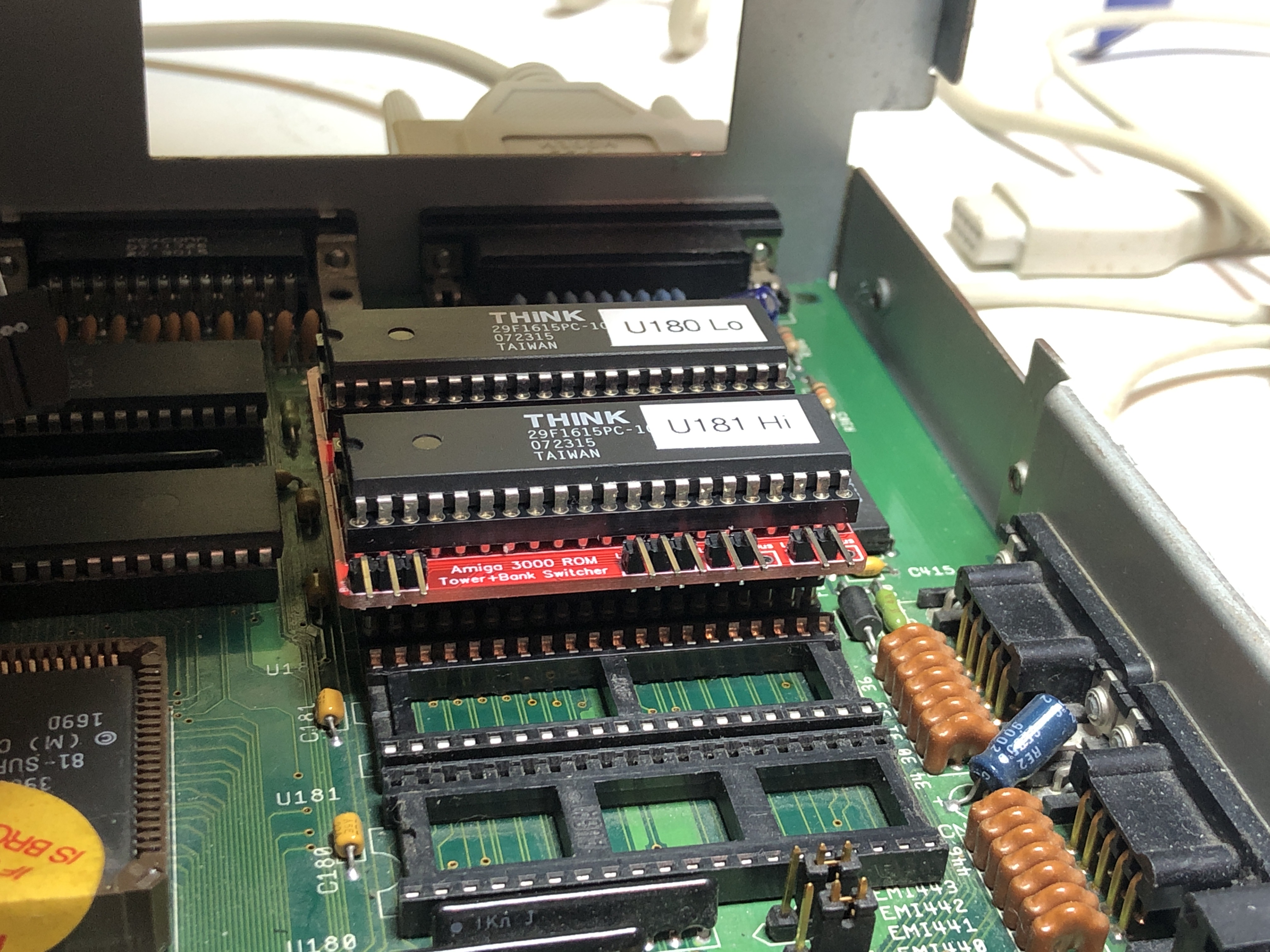 Verify that all header pins on the bottom of the Amiga 3000 ROM Bank Switcher are straight. This is very important, as you will not be able to see all the pins as you insert the board into your Amiga. Align the ROM Bank switcher with the Amiga kickstart sockets, ensuring the notch in the Amiga's sockets match pin 1 of the switcher. Use the photo on the left as a reference for the direction of the board.
Press very slowly, ensuring all pins which are visible around the edge of the board go properly into the Kickstart ROM sockets. I've found that using a magnifier helps a great deal with this task.
You may choose to install your two Kickstart ROMs/EPROMs/EEPROMs before or after the Kickstart switcher is installed in the Amiga. The U180 ROM might be marked as "Low" or "ROM-1". The U181 ROM might also be marked as "High" or "ROM-0".
When done, you should minimally test that there isn't a dead short between GND and 5V with the switcher installed. The easiest way to do this is to check for continuity between pin 22 of either socket and GND of the Amiga (any metal contact from the chassis). If you see less than 5 Ohms, there is a problem (do not power on). Pin 22 is located in the bottom right corner of the two chips, if you look at them from above, with the notch facing to the top (Pin 1: top left corner, Pin 21: bottom left corner, Pin 42: top right corner).
Before fully reassembling your Amiga, I recommend doing a test power-on to verify the ROMs were built and installed correctly. If you've removed your power supply from the frame, the cord to the motherboard may just reach while your power supply is sitting on the edge of the chassis. For the first run, plug in your power supply, hold your finger on the ROMs, and press the power on button. If your Amiga doesn't power on (no green LED), immediately turn it off. If the ROMs get hot, immediately turn it off. If either happens, check that the sockets are installed correctly (for example, not off by a pin). If the Amiga does power on, verify that the power LED toggles from a dim state to a fully powered state. If it does, then you know that Kickstart has run at least far enough that you can confidently reassemble your Amiga.
Installing jumpers on the three headers will select the lowest address 256K block (each) of the two ROMs. Removing the jumpers will select the highest address 256k block of the two ROMs. This gives you access to a 512KB ROM image. If you've installed an enhancement such as Romy (by SpeedGeek) and run a wire from the A17 Bus header to the CPU A19, you will get access to a full 1MB image (ROM A16 pin is CPU A18). A much improved version of Romy can be found at https://github.com/reinauer/amiga-romy.
Enjoy!
| 2MB U180 EPROM (bits 0-15) | |
|---|---|
| 0x000000-0x1fffff | 2MB |
| 2MB U181 EPROM (bits 16-31) | |
|---|---|
| 0x000000-0x1fffff | 2MB |
Note that the ROM address range given in the example above, and all examples that follow, is technically incorrect. Since each EPROM is 16 bits wide (two bytes), the address range for a 2MB EPROM is actually 0x000000-0x0fffff. This may be a bit confusing if you're used to normal 8-bit addressing. So here, and in all the examples that follow, I will use this technically incorrect notation to make the addressing simpler to understand.
That's the good news -- it means more pins for addressing a larger EPROM. Unfortunately it's not enough. The Amiga 3000 was designed and manufactured with 40-pin EPROMs. These EPROMs only have 18 address lines (17 address lines for U182/U183). This limits the amount of ROM space which is addressible in factory-config Amiga 3000 systems.
In fact, with an unmodified Amiga 3000, it looks more like this:
| 2MB U180 EPROM (bits 0-15) | ||
|---|---|---|
| 0x000000-0x1fffff | Usable | 256KB |
| 0x040000-0x1fffff | Wasted | 1792KB |
| 2MB U181 EPROM (bits 16-31) | ||
|---|---|---|
| 0x000000-0x1fffff | Usable | 256KB |
| 0x040000-0x1fffff | Wasted | 1792KB |
A type of trickery -- bank switching.
One thing we can do is "virtually" chop the 2MB EPROMs into 256KB "slots" where each one can be selected by a switch or jumper. Now you can use all the space, but at any given time only one slot is visible. Example (imagine Slot 3 is selected):
| 2MB U180 EPROM (bits 0-15) | ||
|---|---|---|
| 0x000000-0x03ffff | Hidden | Slot 0 |
| 0x040000-0x07ffff | Hidden | Slot 1 |
| 0x080000-0x0bffff | Hidden | Slot 2 |
| 0x0c0000-0x0fffff | Visible | Slot 3 |
| 0x100000-0x13ffff | Hidden | Slot 4 |
| 0x140000-0x17ffff | Hidden | Slot 5 |
| 0x180000-0x1bffff | Hidden | Slot 6 |
| 0x1c0000-0x1fffff | Hidden | Slot 7 |
| 2MB U181 EPROM (bits 16-31) | ||
|---|---|---|
| 0x000000-0x03ffff | Hidden | Slot 0 |
| 0x040000-0x07ffff | Hidden | Slot 1 |
| 0x080000-0x0bffff | Hidden | Slot 2 |
| 0x0c0000-0x0fffff | Visible | Slot 3 |
| 0x100000-0x13ffff | Hidden | Slot 4 |
| 0x140000-0x17ffff | Hidden | Slot 5 |
| 0x180000-0x1bffff | Hidden | Slot 6 |
| 0x1c0000-0x1fffff | Hidden | Slot 7 |
What's not so great about this is that you are still limited to only having access to a 512KB image at a time. "Well, that's the size of all the Kickstart ROMs that Commodore produced for the Amiga 3000, so why would I want more?" Glad you asked.
As Commodore (and later Hyperion) continued adding features and fixing bugs in AmigaOS, the Kickstart image grew larger and larger. At some point, not all of the ROM modules fit anymore. That's okay. As AmigaOS was engineered from the start, it supports loading libraries, filesystems, and other modules from disk either at boot or dynamically as programs require them. The tradeoff, then, is that as AmigaOS has grown larger with newer versions, it takes longer to boot and uses more system RAM. An example of this is with AmigaOS 3.1 on the Amiga 4000T. Having both a SCSI controller and an IDE controller meant including drivers for each in Kickstart so the Amiga could boot from either. Unfortunately, this was a tipping point. There wasn't enough space in the 512KB ROM for both drivers along with all the other runtime ROM code. Something had to give. What happened is that for the Amiga 4000T, workbench.library was jettisoned from the Kickstart ROM and pushed off to disk. An Amiga 4000T running Kickstart 3.1 has to load workbench.library from disk for the OS to get to Workbench.
AmigaOS 3.1.4 from Hyperion, with more features and a lot of fixes, saw the same thing happen to all the other Amiga platforms. Now workbench.library must be loaded into RAM at boot time.
Fortunately, Commodore engineering had some foresight that this was coming. Some of the latest generation Amigas (A1200 and A500+) included 42-pin ROM sockets with more address lines. And, on the software side, Kickstart could be made to probe other addresses than the one 0xf80000 to 0xffffff block.
[Aside: Originally the Kickstart ROM was 256KB in size (Kickstart 1.3 and below). When Commodore designed the A500/A2000, they designed it to handle 512KB ROMs knowing that future Kickstart versions would grow larger than that. When AmigaOS 2.0 came up, this unfortunately left the A1000 behind, with its 256KB hardware WCS.]
What if we could generate a larger Kickstart ROM, and put workbench.library and maybe even several other libraries from disk back into ROM? Is there any benefit? Absolutely! Not only would your Amiga boot faster, but it would have more RAM available as well. Well, sign me up!
This takes us back to the Amiga 3000. It is hardware-limited to 512KB by the fact that it's all the address lines which are present at the Kickstart ROM sockets (U182 and U183). Can't we just add more address lines from the CPU and get more ROM space? Jumper wires aren't so bad. Unfortunately, it's not that easy.
The address range previously described is 0xf80000 to 0xffffff. Where does that come from? The ROM can't tell the difference between 0x0f80000 and 0x10f80000. In fact, in a stock Amiga 3000, the ROM can't tell the difference between 0x0f80000 and 0x0000000. Does the ROM answer at all these addresses? No, it doesn't.
Address decoding is one of Gary's jobs in the Amiga 3000. When Gary sees a CPU address request go by for a read in the Kickstart ROM range (0x0f80000 to 0x0ffffff), Gary does the work of telling the ROM to "pay attention" and output the data. It also tells the CPU, "I've got this" on behalf of the ROM. It does a similar job for other addressible hardware in the Amiga. This address range intelligence is hard-coded into the circuitry of Gary.
That's where the problem lies. Gary was designed to decode 0xf80000 to 0xffffff as the Kickstart ROM range. No more, no less. The ROM will not be enabled, and Gary won't tell the CPU, "I've got this" for another address.
Enter Romy Several years back (2011 or earlier), a very clever individual, SpeedGeek, decided that 512K is not enough. He developed some enhanced logic in a GAL chip that could be added to Amiga 3000 and 4000 computers to give them access to a larger ROM. This enhancement was named Romy, and it added decoding for a different address range, 0xe00000-0xe7ffff to give the CPU access to another 512KB of Kickstart ROM space. See https://eab.abime.net/showthread.php?t=61677 for more information. Newer versions of Romy now have experimental support for even large ROM sizes, up to 4MB, by decoding a larger ROM space. I won't explore the details of how that works. Just be aware that the CPU address lines A19, A20, and A21 can be made useful for accessing more ROM space in the Amiga 3000 and Amiga 4000.
A few examples of the possibilities opened up by the combination of Romy and the Amiga 3000 Rom Bank Switcher are illustrated below. I will combine the U180 and U181 EPROM tables to keep it all on the screen.
Imagine you want to have four different 1MB Kickstart images, which can be selected by switch or jumper settings. Here, the jumpers have been (arbitrarily) set to select Slot 1.
| U180 / U181 EPROM (bits 0-31) | ||||
|---|---|---|---|---|
| ROM Address | CPU Address | Visible? | Size | Slot |
| 0x000000-0x03ffff 0x040000-0x07ffff | 0x0e00000-0x0e7ffff 0x0f80000-0x0ffffff | Hidden | 1MB | Slot 0 |
| 0x080000-0x0bffff 0x0c0000-0x0fffff | 0x0e00000-0x0e7ffff 0x0f80000-0x0ffffff | Visible | 1MB | Slot 1 |
| 0x100000-0x13ffff 0x140000-0x17ffff | 0x0e00000-0x0e7ffff 0x0f80000-0x0ffffff | Hidden | 1MB | Slot 2 |
| 0x180000-0x1bffff 0x1c0000-0x1fffff | 0x0e00000-0x0e7ffff 0x0f80000-0x0ffffff | Hidden | 1MB | Slot 3 |
Q: How is the above configured using Romy and the ROM Bank Switcher?
| Slot | A19 | A18 |
|---|---|---|
| 0 | Low | Low |
| 1 | Low | unset |
| 2 | unset | Low |
| 3 | unset | unset |
Imagine instead that you want a single 4MB kickstart image. You'd first need a Romy configured to support 4MB mode. I believe Stefan Reinauer's Ultimate Romy supports this mode by default.
There is a single memory map in this case.
| U180 / U181 EPROM (bits 0-31) | ||||
|---|---|---|---|---|
| ROM Address | CPU Address | Visible? | Size | |
| 0x100000-0x13ffff 0x1c0000-0x1fffff 0x000000-0x1fffff | 0x0e00000-0x0e7ffff 0x0f80000-0x0ffffff 0x1000000-0x13fffff | Visible | 4MB | |
Q: Where do those ROM addresses come from?
The ROM address is simply a function of the CPU address bits 0-21, but then divided by two because the two ROMs make up the 32-bit wide value. [Remember at the top, we already chose to ignore the fact there are two bytes per ROM. If you want to speak in actual bus terms to the ROM, this would actually mean a further divide by two].
Thus, you can calculate the ROM address with:
ROMaddr = (CPUaddr & 0x380000) >> 1So...
(0x0e00000 & 0x38ffff) >> 1 = 0x00100000 (binary 00010000 00000000 00000000)
(0x0f80000 & 0x38ffff) >> 1 = 0x001c0000 (binary 00011100 00000000 00000000)
(0x1000000 & 0x38ffff) >> 1 = 0x00000000 (binary 00000000 00000000 00000000)
Q: How is the above configured using Romy and the ROM Bank Switcher?
Imagine that you want the option of two 2MB kickstart images. You'd need a Romy which is configured to support 4MB mode.
The possible configurations would be:
| U180 / U181 EPROM (bits 0-31) | ||||
|---|---|---|---|---|
| ROM Address | CPU Address | Size | Slot | |
| 0x000000-0x03ffff 0x0c0000-0x0fffff 0x000000-0x0fffff | 0x0e00000-0x0e7ffff 0x0f80000-0x0ffffff 0x1000000-0x13fffff | 2MB | Slot 0 | |
| 0x100000-0x13ffff 0x1c0000-0x1fffff 0x100000-0x1fffff | 0x0e00000-0x0e7ffff 0x1f80000-0x1ffffff 0x1000000-0x13fffff | 2MB | Slot 1 | |
Q: How is the above configured using Romy and the ROM Bank Switcher?
| Slot | A19 |
|---|---|
| 0 | Low |
| 1 | unset |
Q: Where do those ROM addresses come from?
Similar to the above, the ROM address is simply a function of the CPU address bits 0-20, but then divided by two because the two ROMs make up the 32-bit wide value. The A19/Low jumper ends up selecting bit 20 of the ROM address.
Thus, you can partially calculate the ROM address with:
ROMaddr = (CPUaddr & 0x380000) >> 1and finish by inserting the bit value of A19/Low at bit 20 If A19/Low jumper is installed:
(0x0e00000 & 0x18ffff) >> 1 = 0x00000000 (binary 00000000 00000000 00000000)
(0x0f80000 & 0x18ffff) >> 1 = 0x000c0000 (binary 00001100 00000000 00000000)
(0x1000000 & 0x18ffff) >> 1 = 0x00000000 (binary 00000000 00000000 00000000)
If A19/Low jumper is left open:
(0x0e00000 & 0x18ffff) >> 1 | Bit20 = 0x00100000 (binary 00010000 00000000 00000000)
(0x0f80000 & 0x18ffff) >> 1 | Bit20 = 0x001c0000 (binary 00011100 00000000 00000000)
(0x1000000 & 0x18ffff) >> 1 | Bit20 = 0x00100000 (binary 00010000 00000000 00000000)
More to follow in the future (2 slots of 2MB).