The Rev 4 board is fixes a few minor bugs in the Rev 3 board design, but otherwise retains the same features.
The Rev 3 and Rev 4 board both differ from the Rev 1 and Rev 2 boards in the following ways:
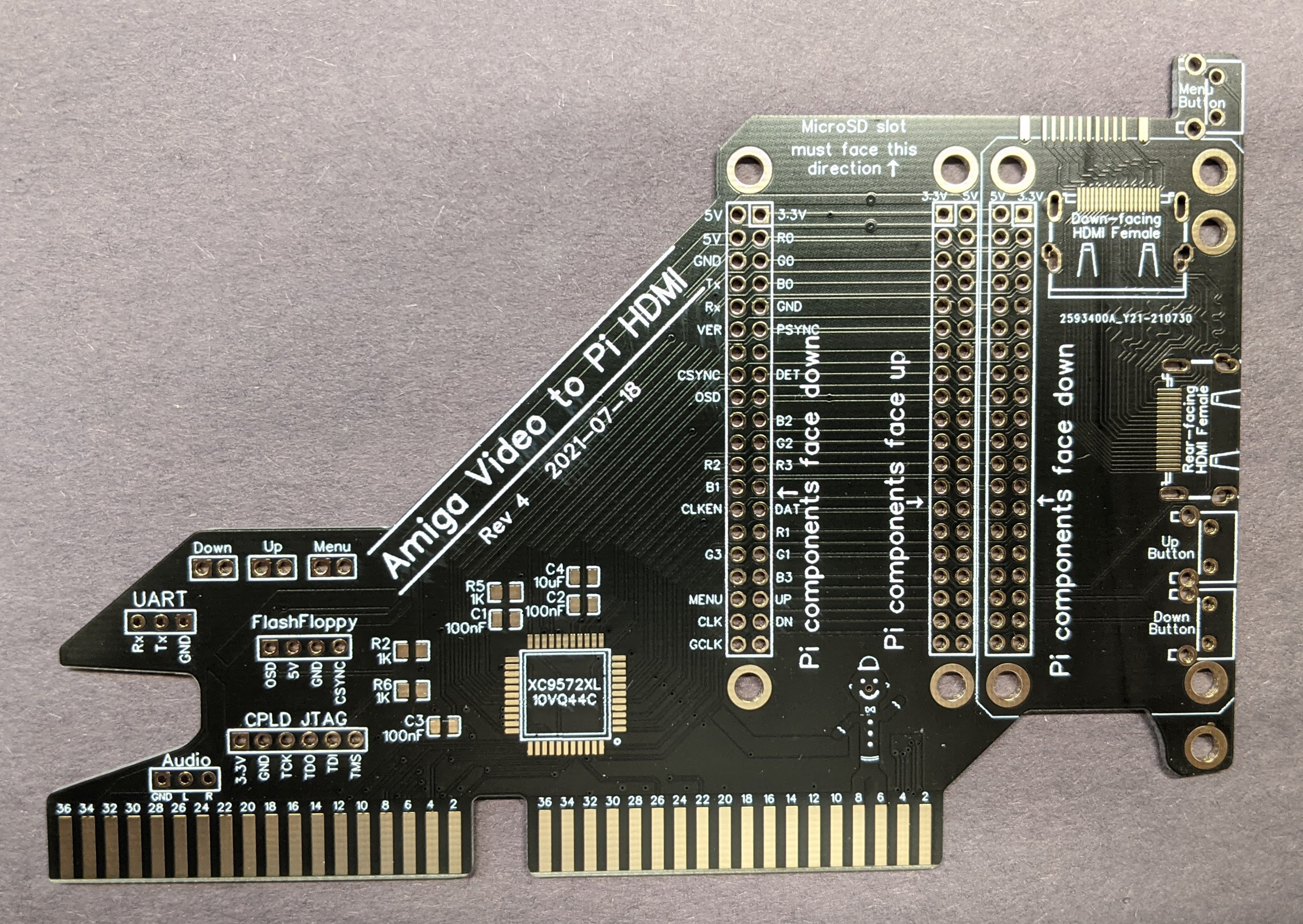
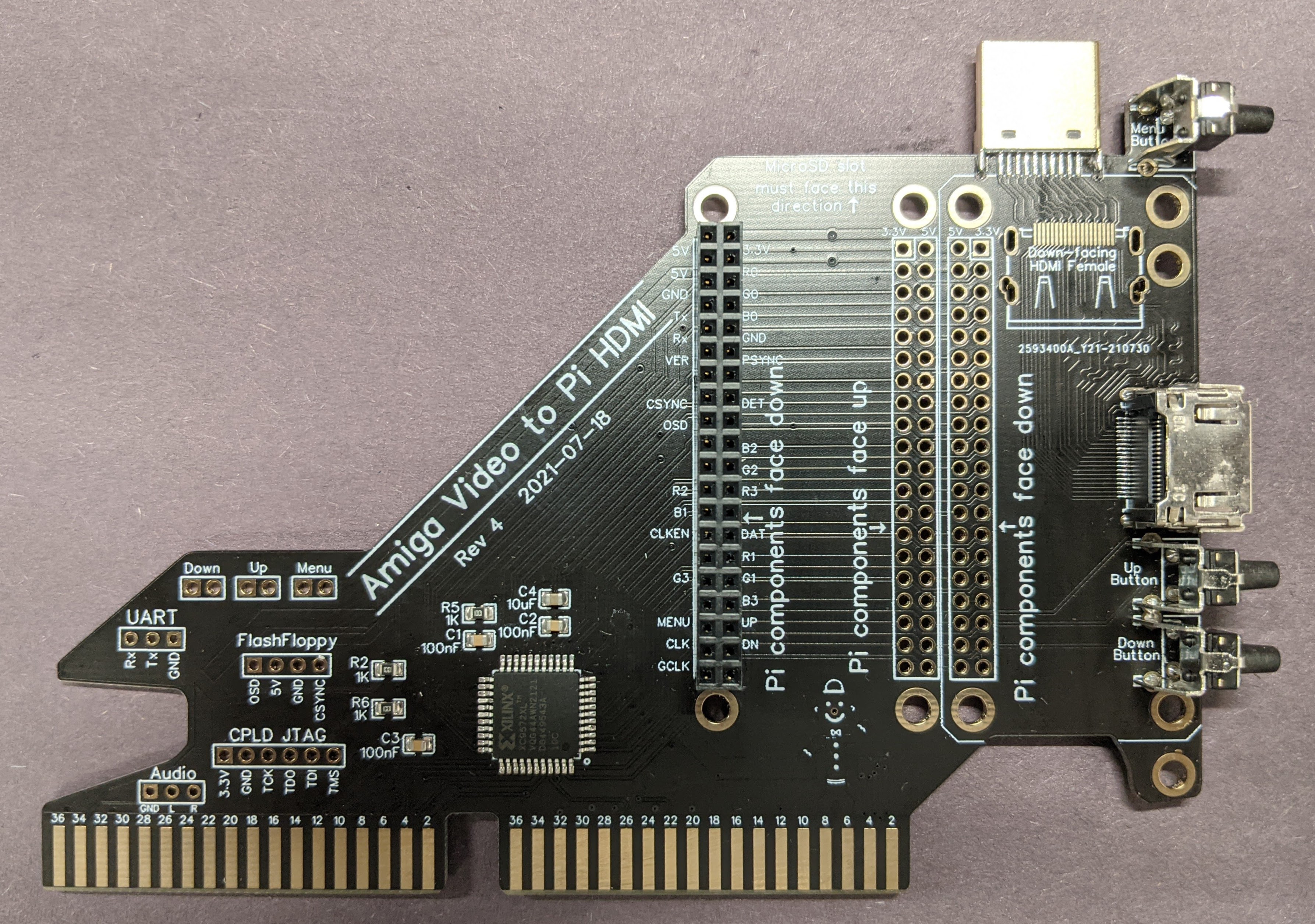
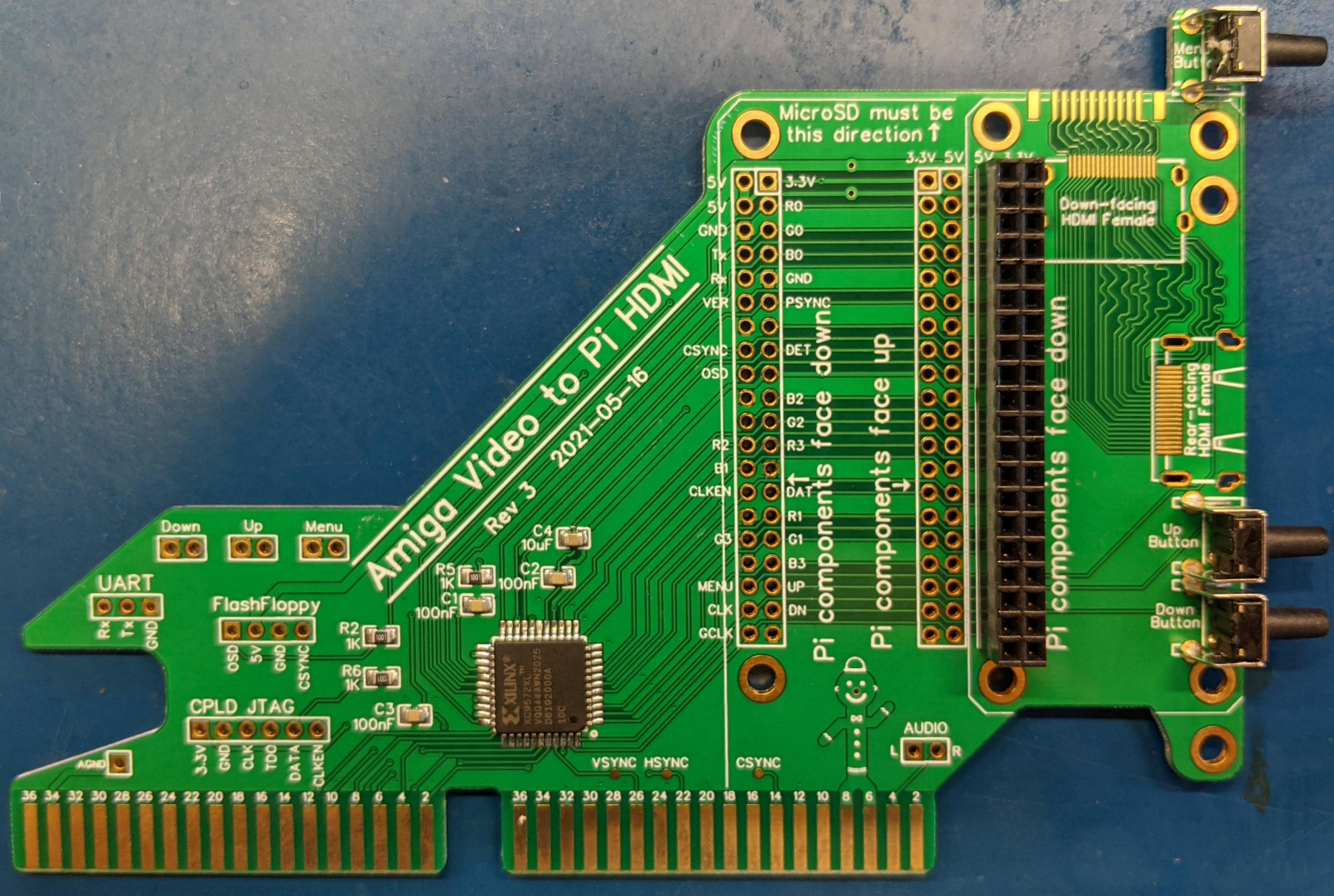
 You will be starting with a blank board, similar to what you see on the left. The first step will be to apply solder paste to all the SMD component pads. On the right you see solder paste applied to most of the SMD component pads. Continue to apply solder paste to all component pads in this area before placing components.
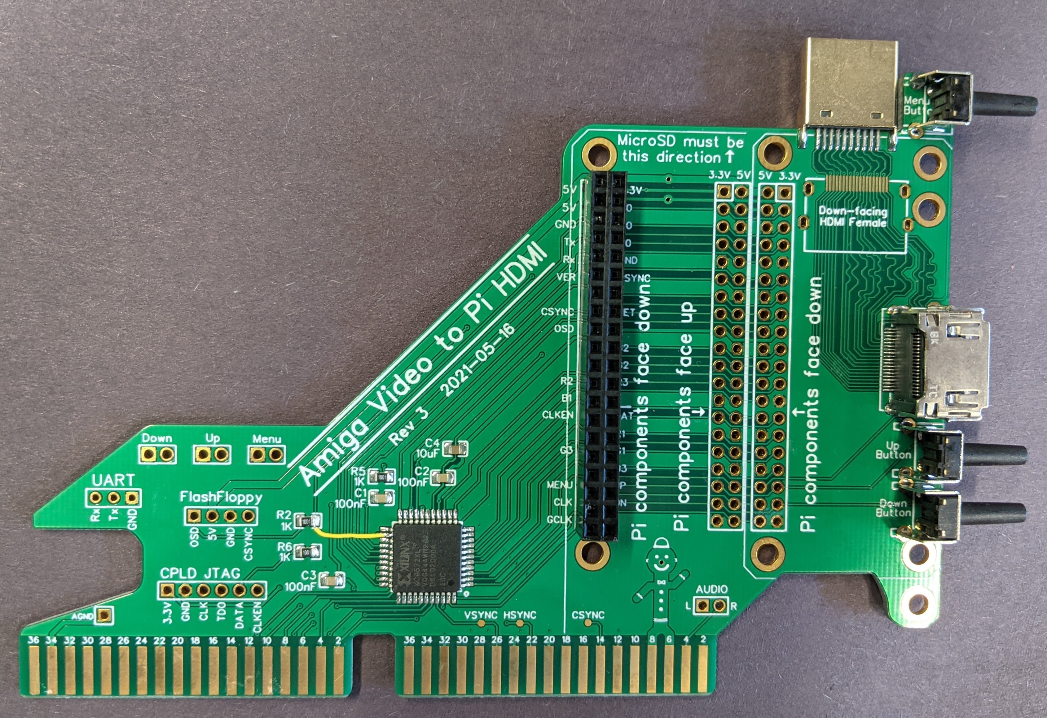
 The next step will be to use hot air to solder down the SMD components. If you don't have a hot air station and solder paste, you can also hand-solder these components. If you're unfamiliar how to do this, search Youtube for "drag soldering" techniques.
The board on the right was soldered down using solder paste and hot air.
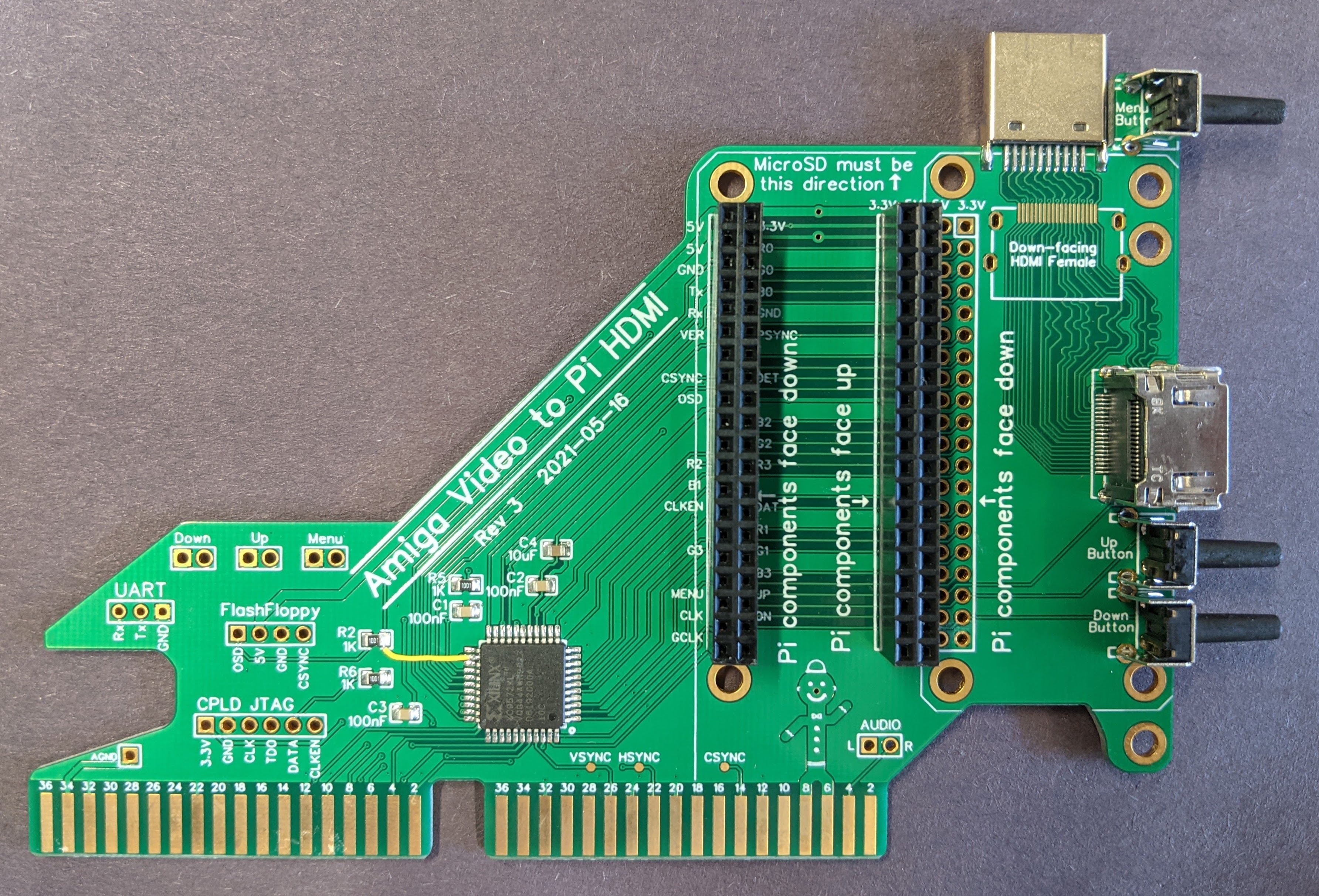
 You will be starting with a board which already has the SMD components installed, similar to what you see on the right.
You'll need the following components for the next step:
You will be starting with a board which already has the SMD components installed, similar to what you see on the right.
You'll need the following components for the next step:
 If you want to use the board's rear-facing full size HDMI port, then you will need to solder down two additional components.
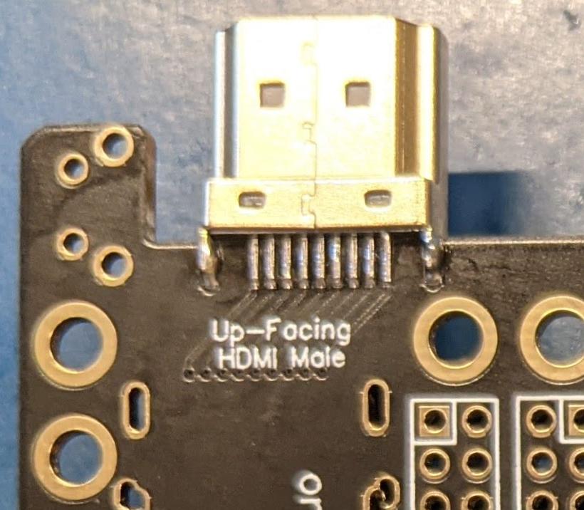
The first is the HDMI male connector which is soldered to the top of the board.
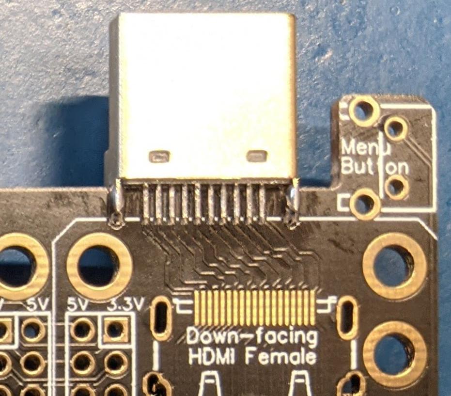
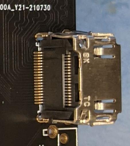
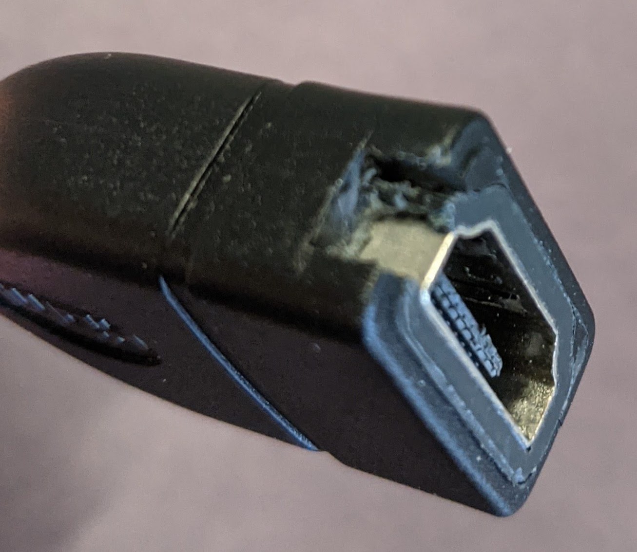
 Second is the HDMI Female connector at the rear of the board.
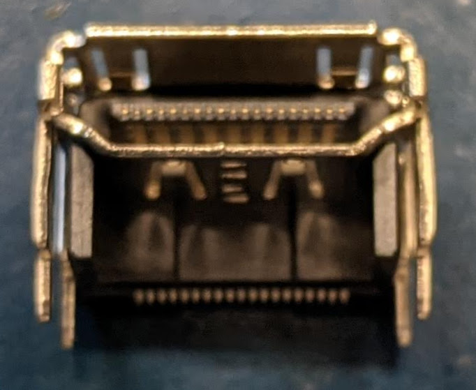
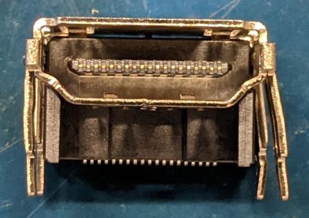
At least with the HDMI connectors I received, the pins do not correctly align with the pads on the board. Luckily, there is a simple fix for this. You'll bend outward the mount pins of one side of the HDMI connector's shell. Then when The HDMI connector sits (tightly) in the holes, the pins will be well-aligned with the pads on the PCB. Notice the original connector on the left side and the adjusted connector on the right side.
Second is the HDMI Female connector at the rear of the board.
At least with the HDMI connectors I received, the pins do not correctly align with the pads on the board. Luckily, there is a simple fix for this. You'll bend outward the mount pins of one side of the HDMI connector's shell. Then when The HDMI connector sits (tightly) in the holes, the pins will be well-aligned with the pads on the PCB. Notice the original connector on the left side and the adjusted connector on the right side.
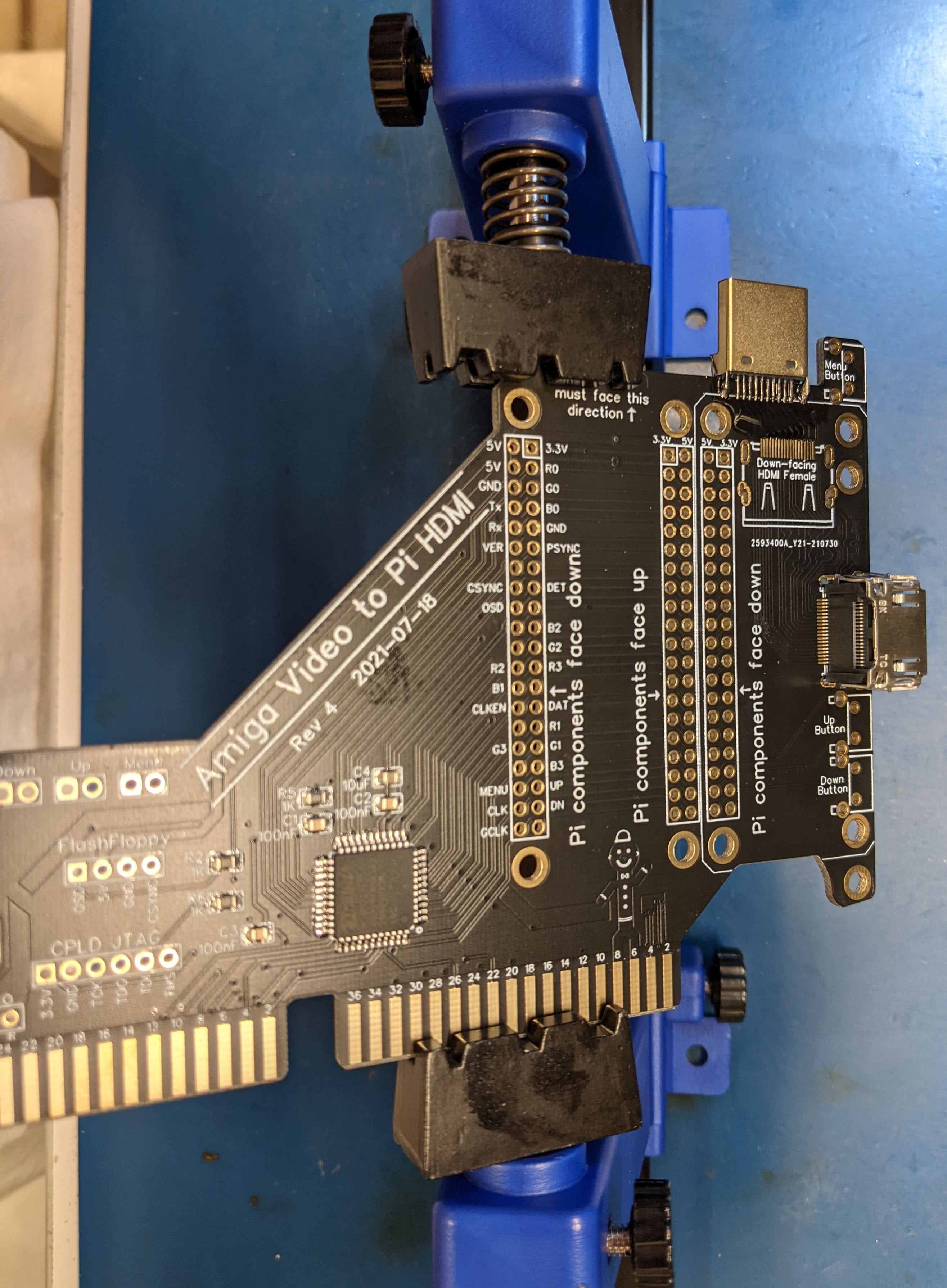
 It might be helpful to use a holder to angle the board such that you can see the very fine pitch pins of the HDMI female connector. A microscope definitely helps here. Be careful not to touch the plastic of the HDMI connector with your iron tip, as it will melt.
To get a good solder bond between the connector and the PCB, you may want to apply solder paste to the pads before placing the HDMI connector.
It might be helpful to use a holder to angle the board such that you can see the very fine pitch pins of the HDMI female connector. A microscope definitely helps here. Be careful not to touch the plastic of the HDMI connector with your iron tip, as it will melt.
To get a good solder bond between the connector and the PCB, you may want to apply solder paste to the pads before placing the HDMI connector.
Once you get the desired alignment of the pads, solder down one of the shield pins to hold the connector in place and inspect to verify the pads are still aligned. Now solder down the remaining shield pins and then signal pins using either hot air or a pencil tip soldering iron.
The HDMI connector pads are very fine pitch. After soldering, inspect the HDMI signal pin soldering thoroughly with a microscope and follow with an ohm meter to detect shorts or poor solder junctions. This is the most common cause of no signal on the HDMI monitor.
The buttons are easy -- either you install three or one or none. If you only have one button, the RGBtoHDMI software may be configured to support that. If you wish to have only one button, mount it in the top position of the board.
The photo on the right shows a board with all three buttons mounted. This is the configuration that I recommend. The menus are easiest to navigate with three buttons.
You'll need to decide where to mount the Raspberry Pi to the Amiga Video to Pi HDMI board. The below uses Rev 3 board photos to show the various options.
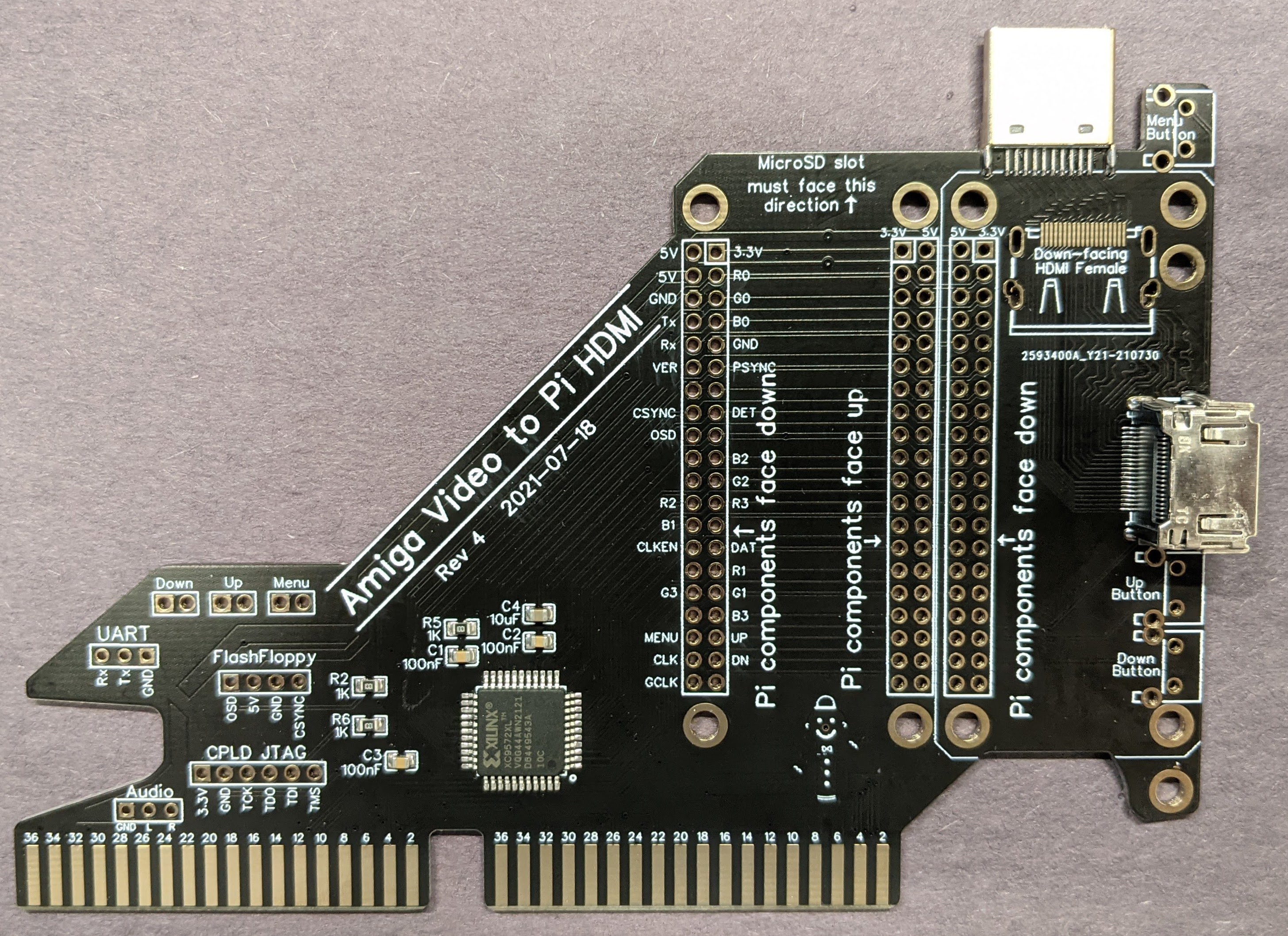
Base your decision on whether you want the Pi's mini-HDMI connector or a full size HDMI connector exposed at the rear of the Amiga. If you want the Pi's mini-HDMI connector exposed at the rear of the Amiga (as seen on the left), this will greatly simplify the work. You just need to mount the female 2x20 pin header in the far right position, as seen in the image on the right. You'll not need to install the two HDMI connectors on the board.

If you instead want a full size HDMI connector exposed at the rear of the Amiga, such as what you see on the left, then you need to mount the female 2x20 pin header in the far left position. The photo on the right shows this.
This configuration involves more components and work, as you will need to solder down two HDMI connectors (a male at the top of the board and a female facing the rear). You will also need a left angle mini-HDMI male to full size female cable.

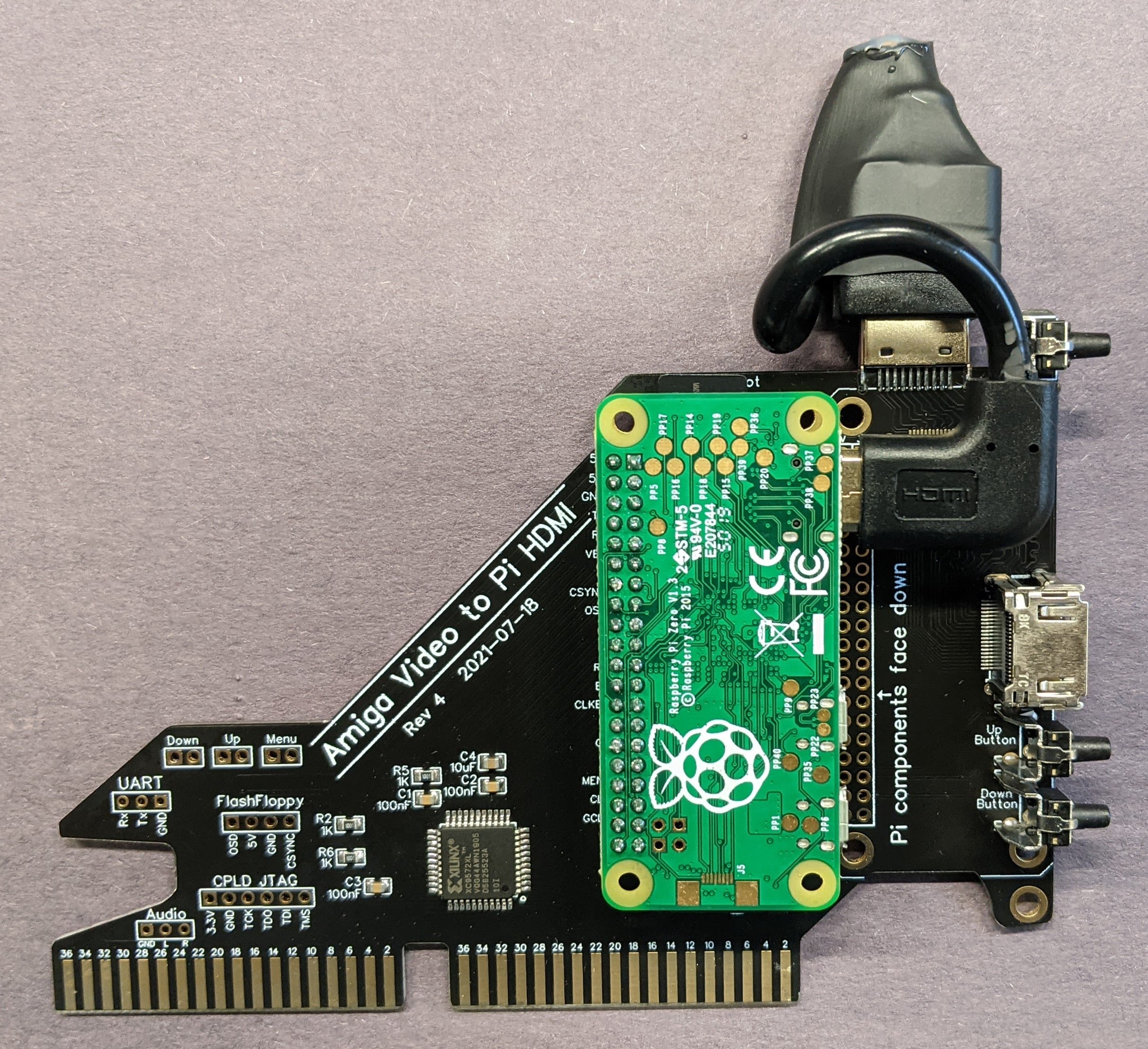
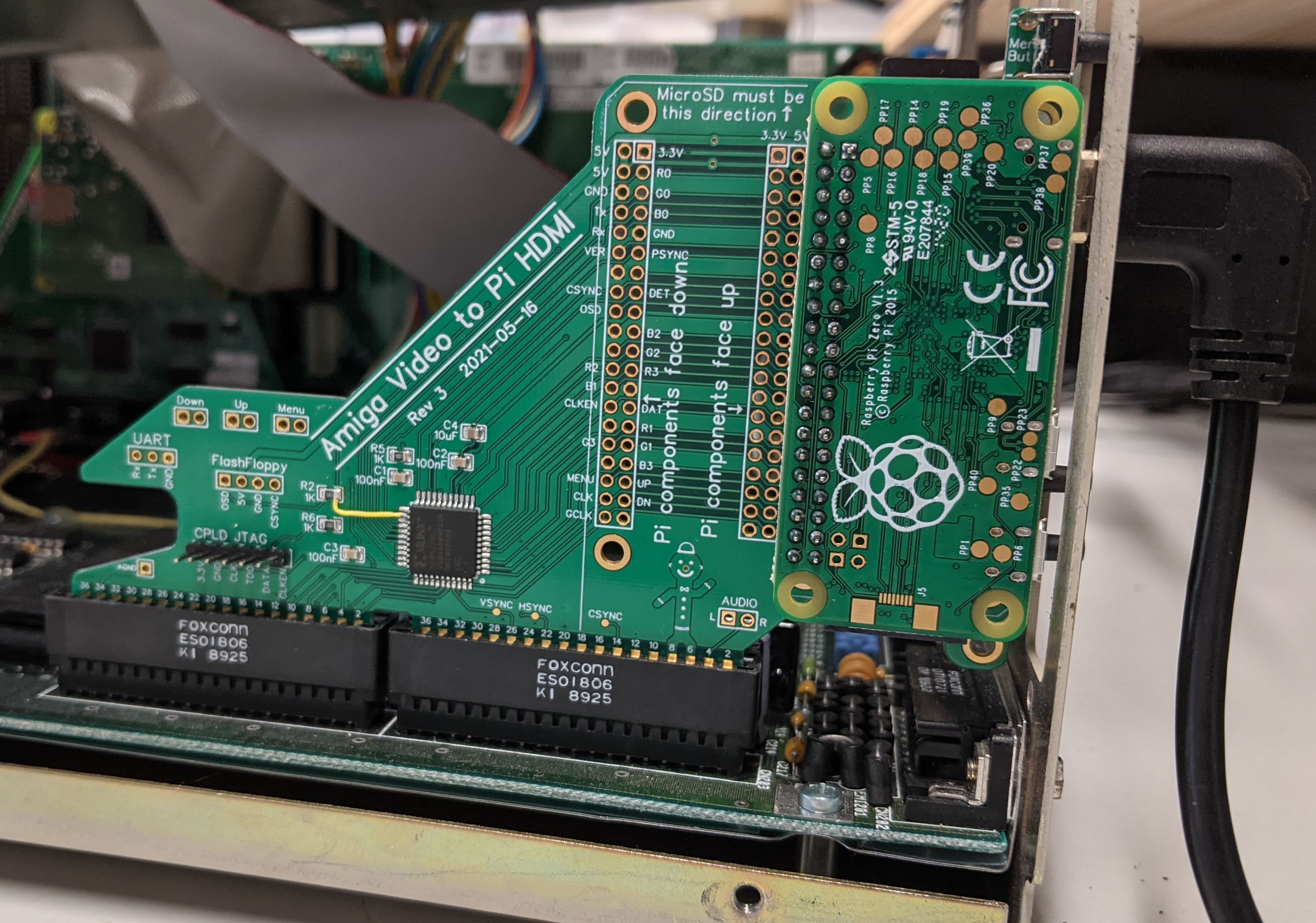
There is another choice, and that is if you happen to have a Pi with the header mounted on the bottom side of the board [The particular Pi in the photo actually has long pins exposed on both sides of the board].
This is what the middle (and only the middle) connector may be used for. You can mount a Pi face-up instead of face-down. Be aware that the Pi microSD card, for all Rev 3 and 4 mounting options, must face away from the card edge. This is a requirement. You can damage your Raspberry Pi and possibly your Amiga if you plug the Pi in upside-down.
The board on the right has two Pi connectors installed. You can either mount the Pi Zero face-down (using the left connector), or face-up (using the middle connector).
 Once you figure out where you want to install the 2x20 pin female header, the actual installation is not too difficult. Insert the header into the desired position and use a piece of tape or tack putty to hold it in place. Flip the board over and solder one pin at an end. Press on the PCB and re-heat the pin to ensure the header is flush to the PCB. Do the same with a pin on the opposite corner of the header. Inspect to be sure the header is flush to the PCB. Now, solder all remaining pins of the header.
The board on the right is using the Pi connector option which would allow a fully size HDMI connector at the rear of the Amiga.
As stated above, you will want a left-angle mini-HDMI male to full-size HDMI female cable. You likely can find these on Amazon or eBay.
With the Rev 3 board, you'd likely need to trim away part of the plastic shroud of the female connector. This is no longer required for the Rev 4 board, as the header on the PCB has been moved to make more room for a larger shroud around the connector.
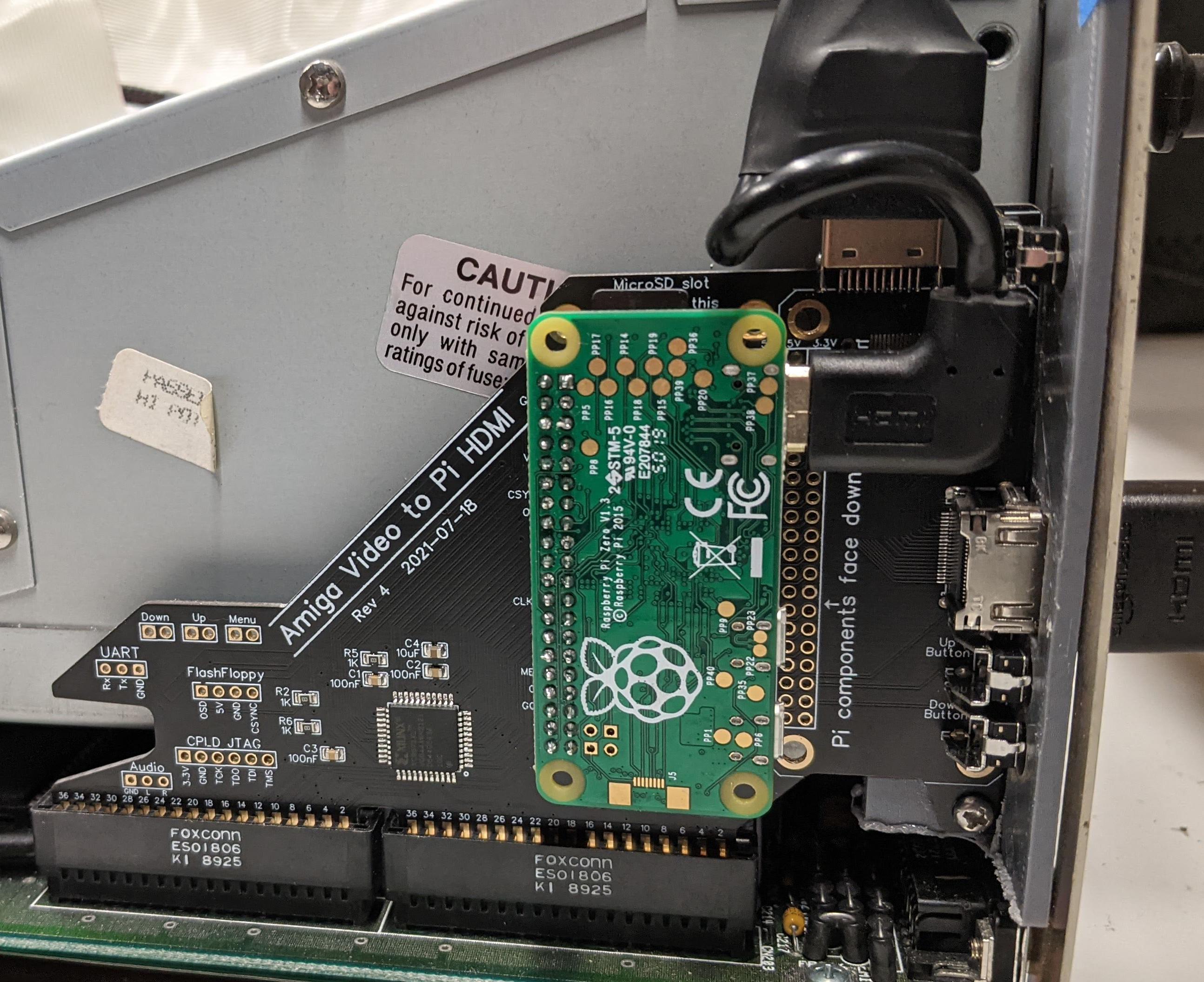
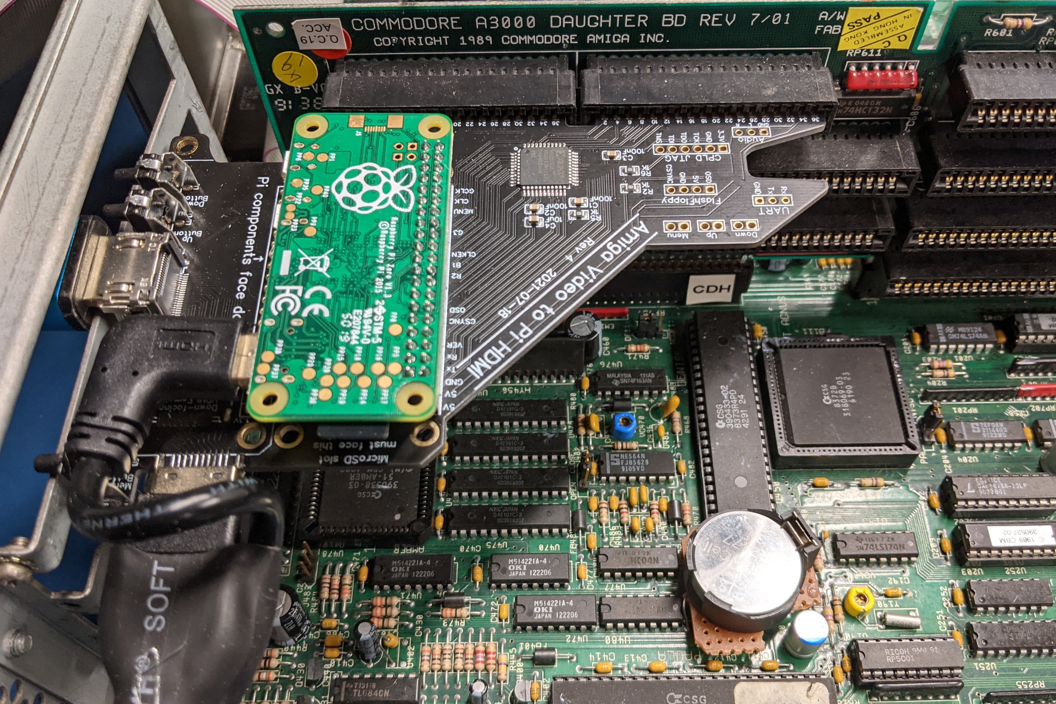 The photo on the left shows a Raspberry Pi installed with the Amiga Video to Pi HDMI board in an Amiga 2000. The photo on the right is a board installed in an Amiga 3000.
You might notice that the board mounted to the Pi to HDMI is a Raspberry Pi Zero. You can also use a Raspberry Pi Zero Wifi (WH), but the Wifi option is not useful for this application. Several vendors sell the Raspberry Pi Zero for a reasonable price, such as CanaKit - AdaFruit - Amazon - eBay
Don't forget to get a 2x20 pin male header with your Raspberry Pi. Amazon eBay
The installed microSD card should have the RGBtoHDMI software, which you can find here: https://github.com/hoglet67/RGBtoHDMI/releases
Simply extract the release Zip file to the root of a blank microSD card. I found that I needed to copy the Amiga_CPLD_Readme/Amiga_2000_CPLD_Setup/profile_6-12_BIT_RGB.txt to the root directory of the microSD card before unmounting it from the computer. No other changes were necessary.
The first time you start up your Amiga with the Amiga video to Pi HDMI board installed, you will need to program the CPLD. You can do this using software on the Raspberry Pi. In fact, the RGBtoHDMI software should detect that the CPLD is not programmed and offer a programming menu. If it doesn't do that, After the Raspberry Pi has booted (just a few seconds), press the top button. The on-screen menu should appear. Use the middle button to move the cursor (arrows) down to the CPLD Recovery Menu. Press the top button to enter the CPLD Recovery Menu. Press the middle button until you reach the latest 6-12_BIT_RGB_CPLD_vXX firmware version, then press the top button to select it. Press the top button a second time to confirm, and the CPLD will be programmed. After this, you may need to power cycle your Amiga for the CPLD to begin using the new firmware. You should then see the Amiga's screen on the HDMI output of the Raspberry Pi.
If your Amiga video output from the Pi is unstable at this point, you should check that the correct Profile and Sub-Profile are set. Press the top menu button to enter the Main Menu. Press the middle button until you reach the Profile. In the case of my 60MHz NTSC Amiga 2000 and Amiga 3000, I found that Amiga 2000 works best for the Profile. You should also set the Sub-Profile. For the same Amiga, I found that Amiga 2000 60Hz is the best Sub-Profile for NTSC Amigas. After you find a profile which gives good video, be sure to use the Save Configuration menu option to save it so that your Pi will use it from cold power-on.
You can test whether the save was successful by rebooting the Pi. Go to the Information menu and select Reboot. Once the profile is configured, you should see good video sync, but there might be observable sparkle. This can be eliminated by fine tuning the sampling phase. Go to the Sampling menu and change the Sampling Phase value until no more sparkle is visible. In my Amigas, a number of 4 or 5 seems to work pretty well for the Sampling Phase.
Please check out LinuxJedi's excellent Github repository for his CPLD version of AmigaRGBtoHDMI. Most of the CPLD programming and software installation instructions are directly applicable to this board.