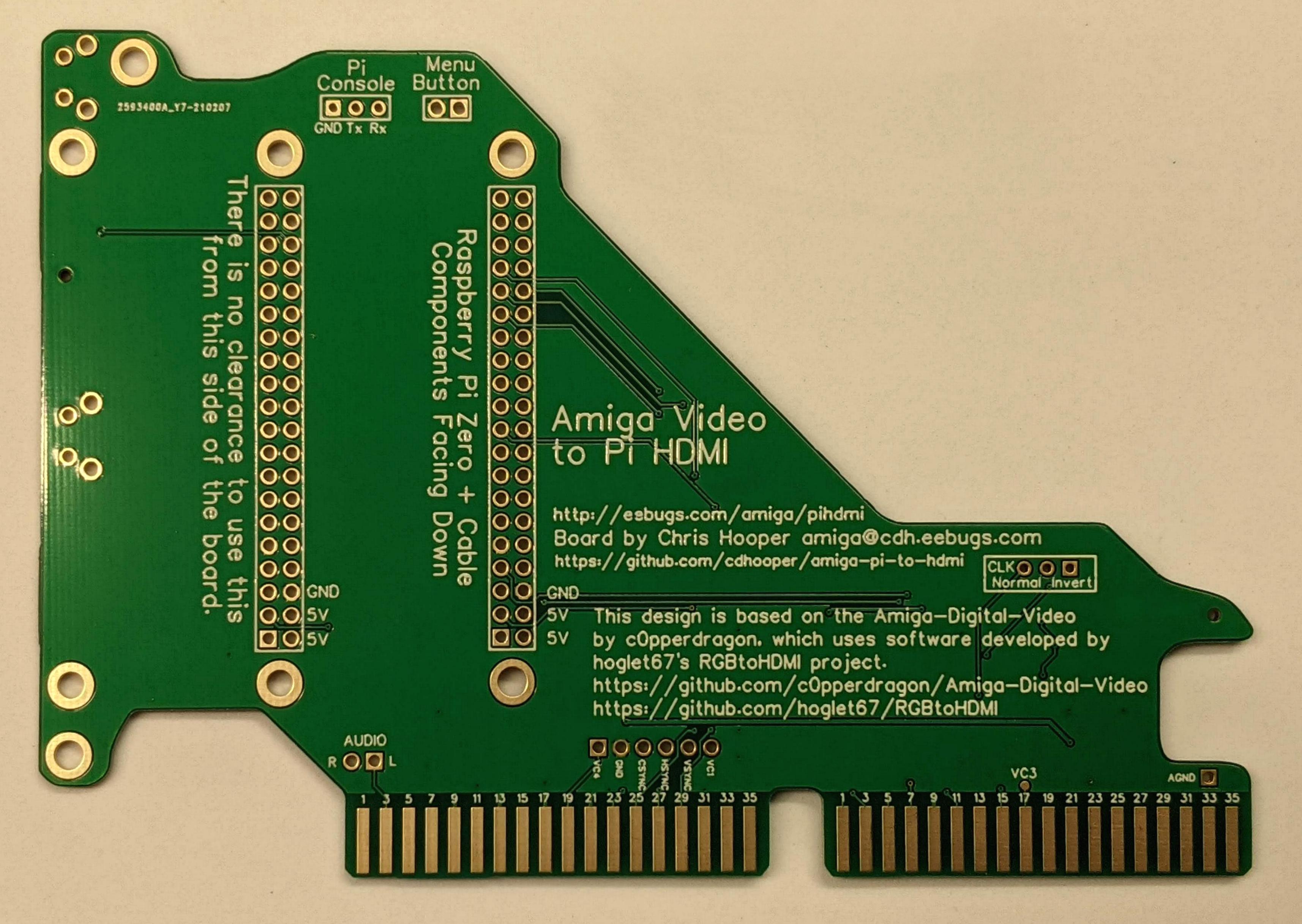
You will be starting with a board which already has the SMD components installed, similar to what you see on the right.
You'll need the following components for the next step:
If you install the Pi Zero in the position which is further away from the rear of the board, you can add a right angle Mini HDMI to full size HDMI adapter and then route that to the rear of your Amiga.
Another option would be to install the 2x20 pin female on the bottom side of the Amiga Video to Pi HDMI board. If you do this, then you will mount the Pi Zero face down to the bottom of the Amiga Video to Pi HDMI board.
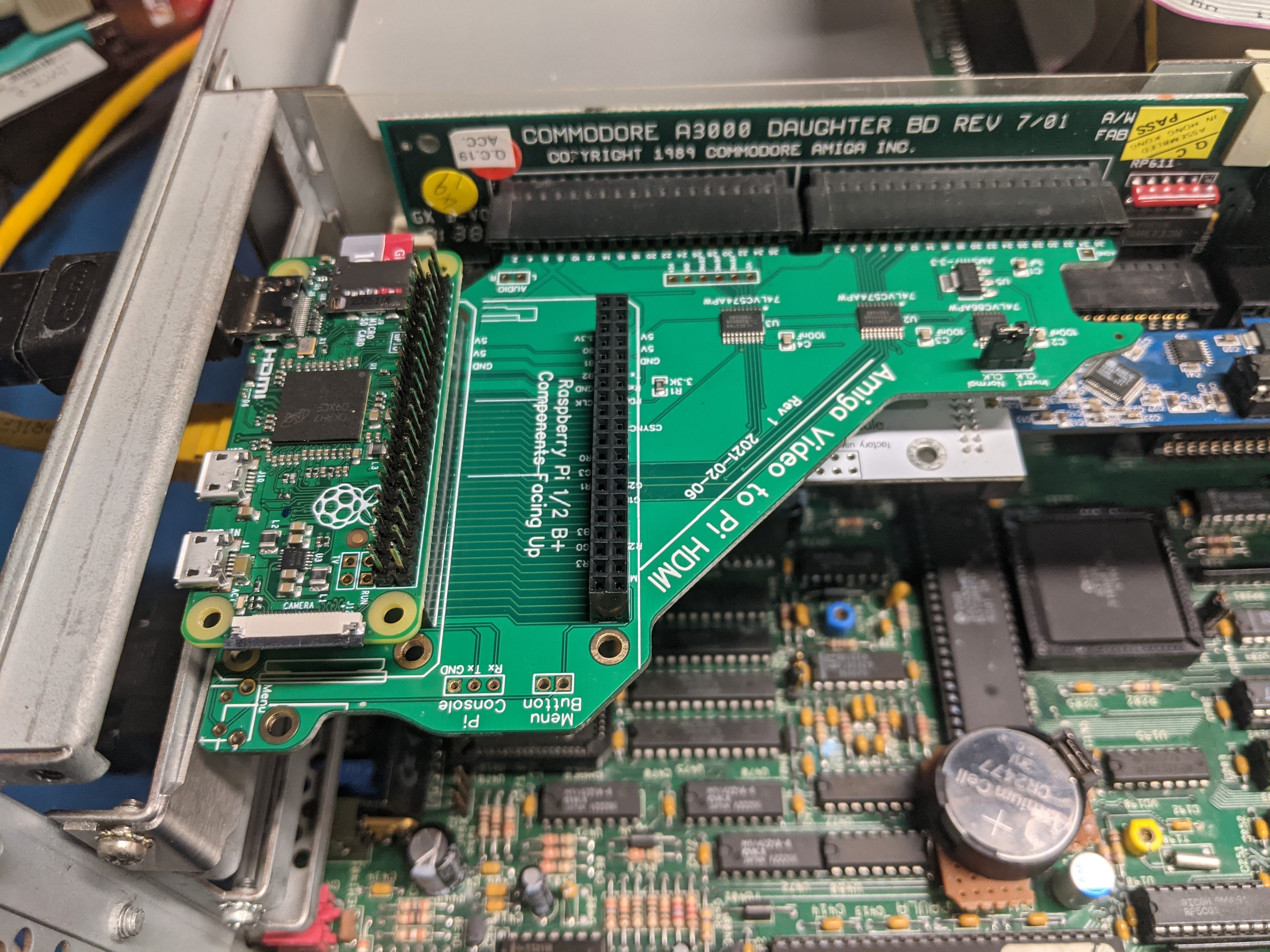 To the right is an example of a Pi Zero installed on the Amiga Pi to HDMI with the Mini HDMI connector exposed through the rear of an Amiga 3000 video slot. Note that the Pi Zero is installed face-up, as previously described.
Once you have the Pi header installed, the next step will be to install the 1x3 header for the CLK pins. As noted above, this is not useful in Rev 1, so you may choose to just short by a jumper wire the "Normal Clk" and center pin of that header.
If you have a 6x6 right angle tactile button, you may choose where to install that button -- either at the top rear of the board, or in the middle rear. If you choose to install in the middle rear, you must verify there is sufficient clearance under the Pi Zero so that the metal shell of the button doesn't make contact with the bottom of the Pi.
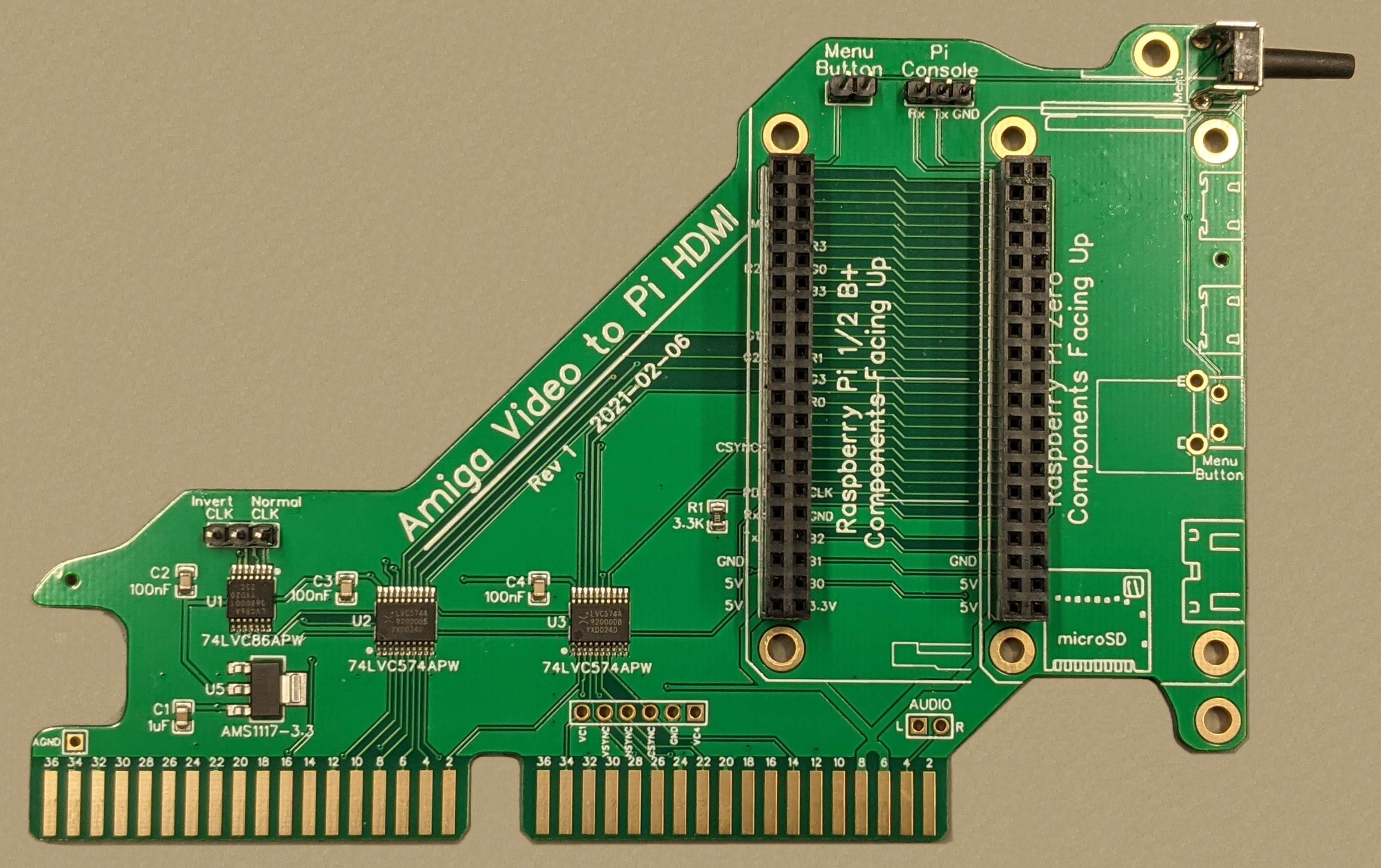
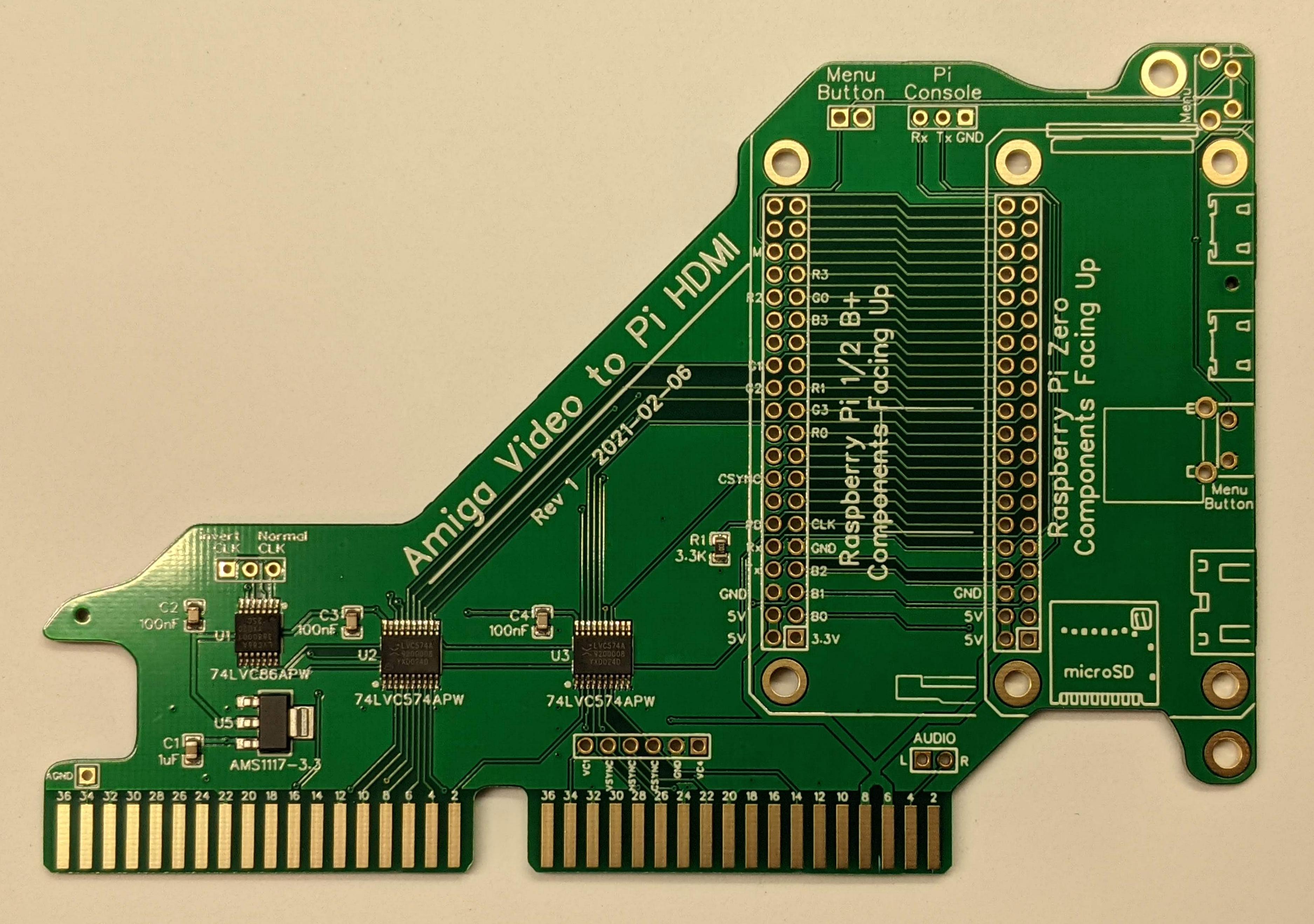
As you can see from the photo on the right, I've chosen to install the button at the top rear of the board.
You might also note that I've also installed both 2x20 pin Pi connectors, the Menu button header, the "Pi Console" header, and the Invert/Normal CLK Header.
Be aware that the board will not work as it is, because there needs to be a jumper installed between the Normal CLK and the center position of that header.
As to installing software for the Pi, you will need a microSD which is compatible with the Raspberry Pi. I've run into microSD cards which are not compatible (I'm looking at you, Cloudisk). You can get the latest version of the Pi software from hoglet67's RGBtoHDMI repository in Github.
I also suggest checking out the excellent Amiga-Digital-Video project in Github. This project is what inspired me to create an Amiga video slot version of the Denise adapter.
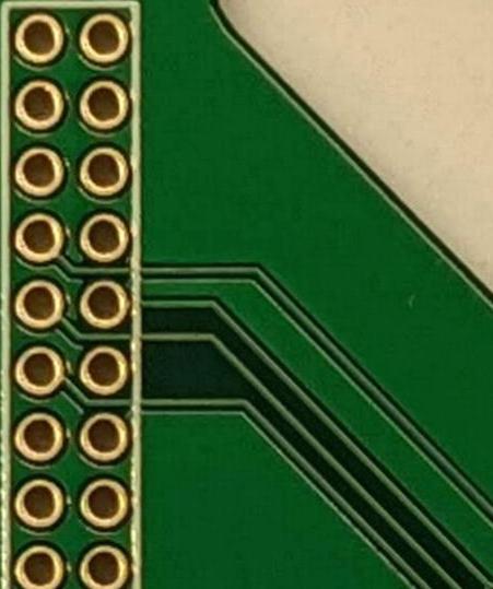
The easiest access to these traces is from the bottom side of the board.
Start by flipping the board over. Observe the area of the board shown on the right.
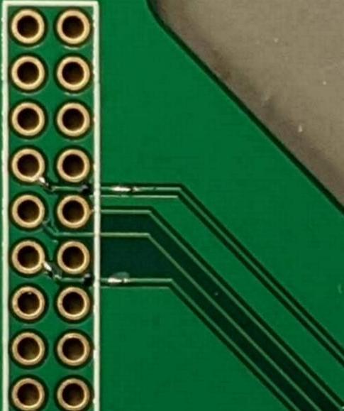
 Start by cutting the top and bottom traces. I've had success using a Dremel with a fine tip grinding bit. On the left, the traces have been cut and UV resist has been applied to cover the exposed copper. The copper has been tinned with solder to get it ready for the jumper wires.
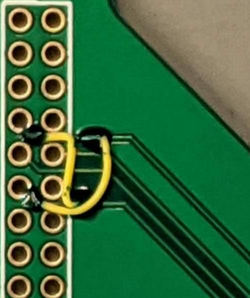
On the right, jumper wires have been soldered down, effectively swapping the traces.
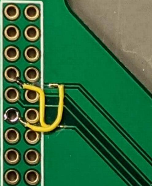
On the far right, UV solder mask has been applied to hold the jumper wires in place.
You're done! This is all that is necessary to get the Rev 1 board to work properly in an Amiga with OCS Denise (8362). Be sure you set the jumper to Normal CLK.
My understanding is that Commodore changed the clock source for ECS Denise from CDAC to 7M. CDAC is 90 degrees out of phase from 7M, so you may see some color fringing if the Amiga Video to Pi HDMI is clocked from CDAC with an ECS Denise.
There are a few solutions at this point: